A
B
C
D
E
F
G
H
L
M
N
P
Ruote - Sospensioni - Freni
Wheels - Suspensions - Brakes
sezione / section
G 6
36 749/749 DARK/749S Aggiornamento/Update - M.Y. 2006 - edizione/edition 00
Smontaggio impianto
freno posteriore
Prima di procedere alla rimozione dei
componenti in questione occorre
rimuovere dal motoveicolo i
particolari riportati di seguito:
Svitare e rimuovere la vite speciale (5)
di fissaggio della tubazione (A) alla
pinza freno posteriore (3) e
recuperare le guarnizioni (4).
Svitare le viti (13) e staccare le
fascette (12) in modo da liberare il
tubo (A) dal forcellone posteriore.
Rimuovere la tubazione (A),
liberandola dalle fascette di ritegno
del cavo (B) sensore velocità (8).
Svitare le viti (6) di fissaggio pinza
freno posteriore (3), alla piastra
portapinza (10) e rimuoverla.
Note
Per le operazioni di sostituzione
delle pastiglie freno (15) seguire
quanto riportato al paragrafo
“Controllo usura e sostituzioni
pastiglie freno” (Sez. D 4).
Importante
La casa costruttrice delle pinze
e delle pompe freno, considerando
l'importanza in termini di sicurezza
che rivestono questi componenti,
suggerisce di non intervenire in
nessun modo all'interno della pinza o
della pompa. Una revisione non
eseguita correttamente può mettere
in serio pericolo l'incolumità del pilota.
Le operazioni di sostituzione sono
limitate a:
Pinza: Pastiglie, componenti di
fissaggio e gruppo di spurgo.
Pompa: pedale di comando, gruppo
di spurgo, serbatoio e componenti
(Sez. F 4).
Per rimuovere il sensore velocità (8),
svitare la vite (7) di fissaggio alla
piastra portapinza, facendo
attenzione al distanziale (9).
Operazioni Rif. Sez.
Rimuovere la carena
laterale destra
E 2
Svuotare il circuito
freno posteriore
D 4
Rimuovere la vite
speciale di fissaggio del
tubo freno alla pompa
freno posteriore
F 4
Rimuovere la ruota
posteriore
G 4
Removing the rear brake
system
Before removing the parts in question,
you must first remove the following
parts:
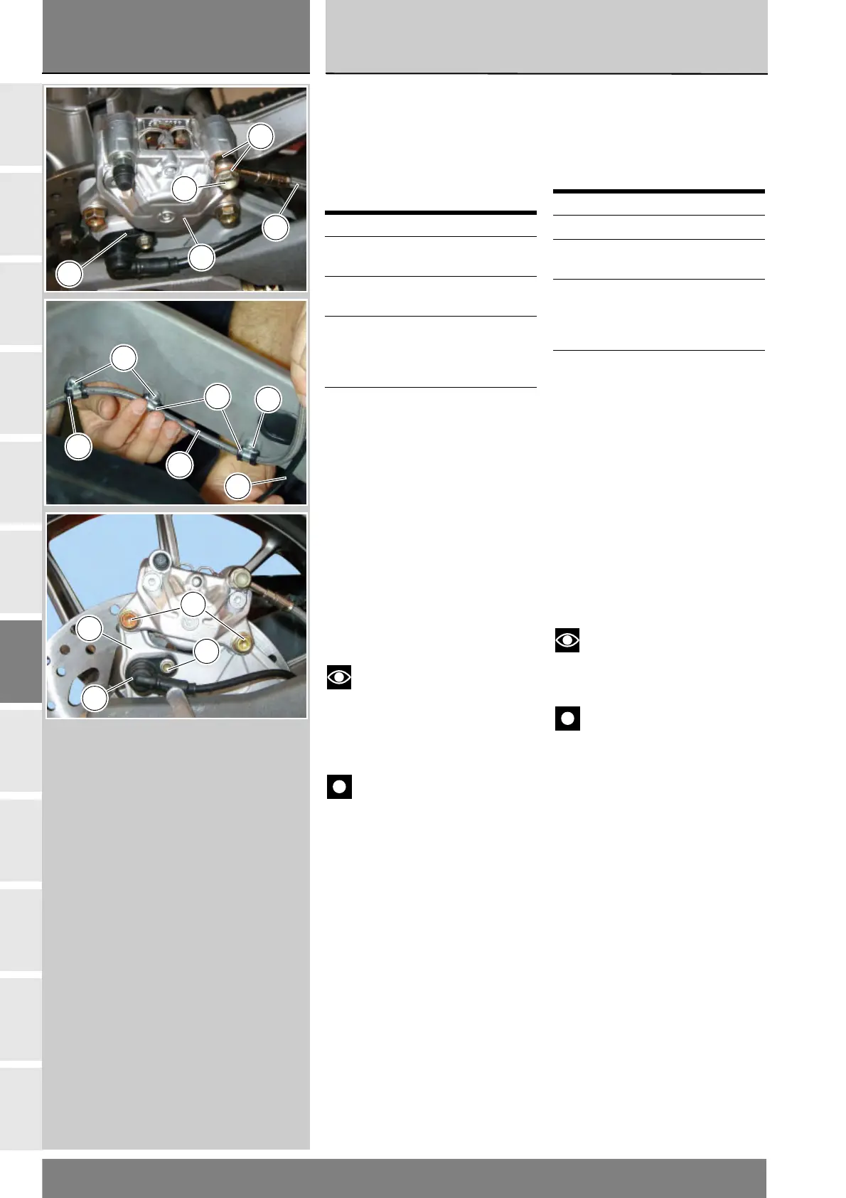
Undo and remove the special screw
(5) securing the pipe (A) to the rear
brake calliper (3) and recover the
gaskets (4).
Undo the screws (13) and detach the
clips (12) so as to free the pipe (A)
from the rear swingarm.
Remove the pipe (A), releasing it
from the clips securing the cable (B)
of the of the speed sensor (8).
Unscrew the screws (6) securing
the rear brake calliper (3) to the
calliper mounting plate (10) and
remove the calliper.
Notes
To change the brake pads (15),
refer to “Checking brake pad wear
and replacement” (Sect. D 4).
Important
Critical safety components.
The brake calliper manufacturer
advises against servicing the internal
components of callipers or the
master cylinder. Incorrect overhaul
of this critical safety component
can endanger rider safety.
Only the following parts should be
replaced:
Calliper: Pads, fasteners and bleed
assembly.
Master cylinder: control pedal,
bleed assembly, reservoir and its
parts (Sect. F 4).
To remove the speed sensor (8),
undo the screw (7) securing it to the
calliper mounting plate, taking care
not to damage the spacer (9).
Operation See Sect.
Remove RH side fairing E 2
Drain the rear brake
circuit
D 4
Remove the special
screw securing the
brake pipe to the rear
brake master cylinder
F 4
Remove the rear wheel G 4
9
3
A
4
5
13
12
13
12
A
B
10
6
7
8