A
B
C
D
E
F
G
H
L
M
N
P
Impianto elettrico
Electric system
sezione / section
P 2
27749/749 DARK/749S Aggiornamento/Update - M.Y. 2006 - edizione/edition 00
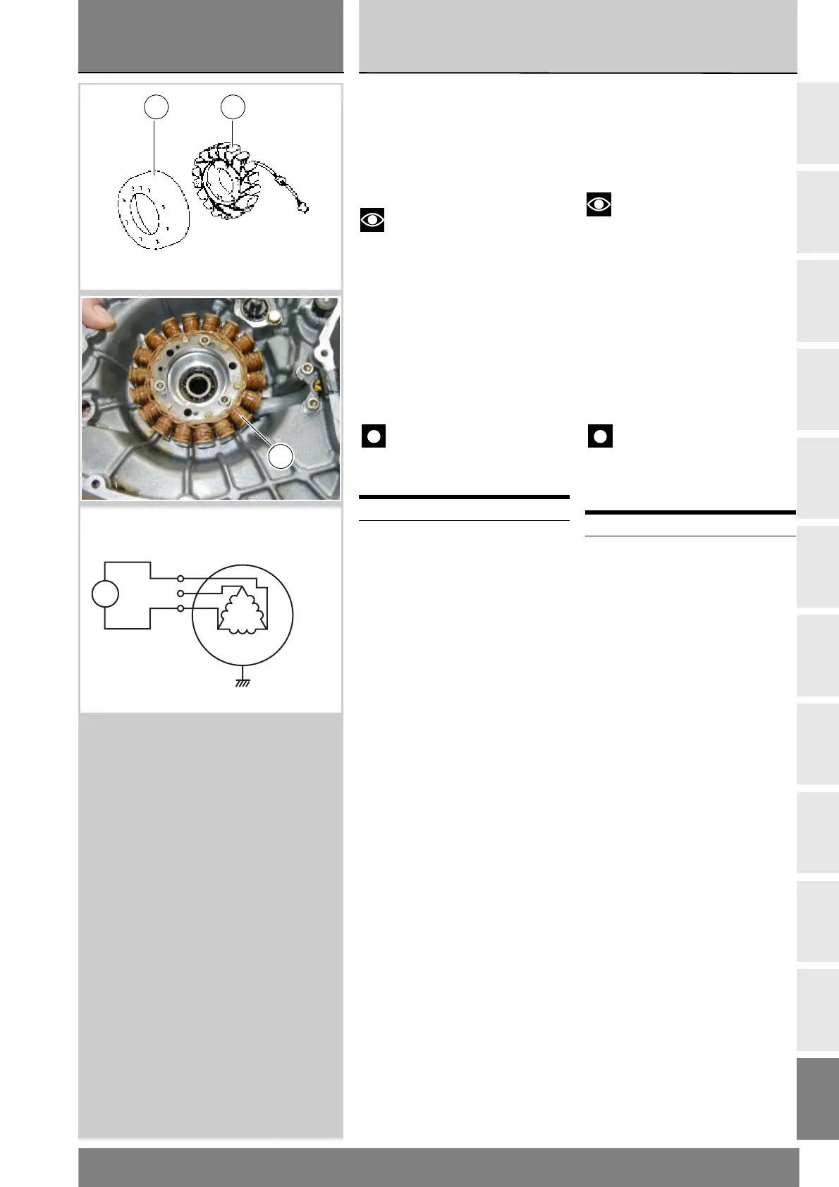
Generatore
È costituito da un alternatore a 12V
con potenza di 480W, composto da un
elemento fisso (statore, A) situato nel
coperchio alternatore e da uno mobile
(rotore, B) solidale all’albero motore.
Note
Per il controllo della difettosità
dell'impianto di ricarica utilizzare lo
strumento di diagnosi “DDS”,
seguendo le indicazioni riportate al
paragrafo “Controllo corrente
impanto di ricarica” (Sez. D 5).
Il valore assoluto della tensione
efficace misurata ai capi di due dei tre
cavi gialli (il valore rilevato é uguale in
tutte le combinazioni) deve rientrare
nei valori indicati nella tabella.
Importante
Scollegare e collegare i cavi
dell'alternatore dall'impianto con quadro
spento (chiave in posizione OFF).
Valori decisamente inferiori a quelli
riportati possono essere causati da:
Rotore parzialmente smagnetizzato.
Spire dell’avvolgimento in corto circuito.
In questi casi l’intero generatore (rotore
e statore) deve essere sostituito.
Se le verifiche effettuate hanno
dato esito positivo, ricollegare il
generatore al regolatore sempre
con chiave accensione in posizione
OFF, accertandosi che non vi siano
cavi spelati o non connessi.
Smontaggio generatore
Rimuovere la carena sinistra (Sez. E 2).
Scollegare i cavi dell’impianto
elettrico lato alternatore (Sez. P 1).
Rimuovere il supporto batteria
(Sez. M 3). Rimuovere il coperchio
alternatore (Sez. N 8).
Rimuovere lo statore (A) (Sez. N 8).
Rimuovere il rotore (B) (Sez. N 8).
Rimontaggio generatore
Rimontare il rotore (B) (Sez. N 8).
Rimontare lo statore (A) (Sez. N 8).
Rimontare il coperchio alternatore
(Sez. N 8). Rimontare il supporto
batteria (Sez. M 3).
Collegare i cavi dell’impianto
elettrico lato alternatore (Sez. P 1).
Rimontare la carena sinistra (Sez. E 2).
Giri motore 1000 6000 8000
V19109144
Generator
The generator is a 12V, 480W
alternator, consisting of a stator (A)
located in the generator cover and a
rotor (B) fixed to the crankshaft.
Notes
To check the charging system
for faults, use the DDS tester and
follow the instructions given under
the heading “Checking the charging
system current” (Sect. D 5).
The absolute value of the voltage
measured across the terminals of
two of the three yellow cables (the
measured value will be the same
whichever the combination) must
be within the range indicated in the
table below.
Important
Disconnect and connect the
generator cables from the system
with the instrument panel switched
off (key OFF).
Values notably lower than those
indicated above can be due to:
partially demagnetised rotor.
short-circuited coil windings.
In the above cases the whole generator
assembly (rotor and stator) should be
replaced.
If checks have a favourable outcome,
reconnect the generator to the
regulator with ignition key on OFF.
Make sure that no cables are
damaged or disconnected.
Removing the generator
Remove the LH side fairing (Sect. E 2).
Disconnect the electrical system
wires on the generator side (Sect. P 1).
Remove the battery mount (Sect. M 3).
Remove the generator cover (Sect. N 8).
Remove the stator (A) (Sect. N 8).
Remove the rotor (B) (Sect. N 8).
Refitting the generator
Refit the rotor (B) (Sect. N 8).
Refit the stator (A) (Sect. N 8).
Refit the generator cover (Sect. N 8).
Refit the battery mount (Sect. M 3).
Reconnect the electrical system wires
on the generator side (Sect. P 1).
Refit the LH side fairing (Sect. E 2).
Engine rpm 1000 6000 8000
V 19 109 144
B A
A
1
2
Y
Colore cavi:
Y=giallo
Y=yellow
AC= Asse generatore
AC= Generator assy
V
~
Y
Y
3