A
B
C
D
E
F
G
H
L
M
N
P
Motore
Engine
sezione / section
N 9.2
169 749/749 DARK/749S - M.Y. 2005 - edizione/edition 00
Spessorazione alberi
Prima di procedere con la chiusura dei
semicarter è necessario eseguire il
calcolo dei rasamenti che determinano
il gioco assiale dell'albero motore e
degli alberi gruppo cambio.
Eseguire il calcolo dei rasamenti
seguendo le procedure a seguito
descritte.
Spessorazione albero motore
Dopo aver installato i cuscinetti di
banco nuovi procedere nel modo
seguente per determinare la quota
“SA” totale delle spessorazioni:
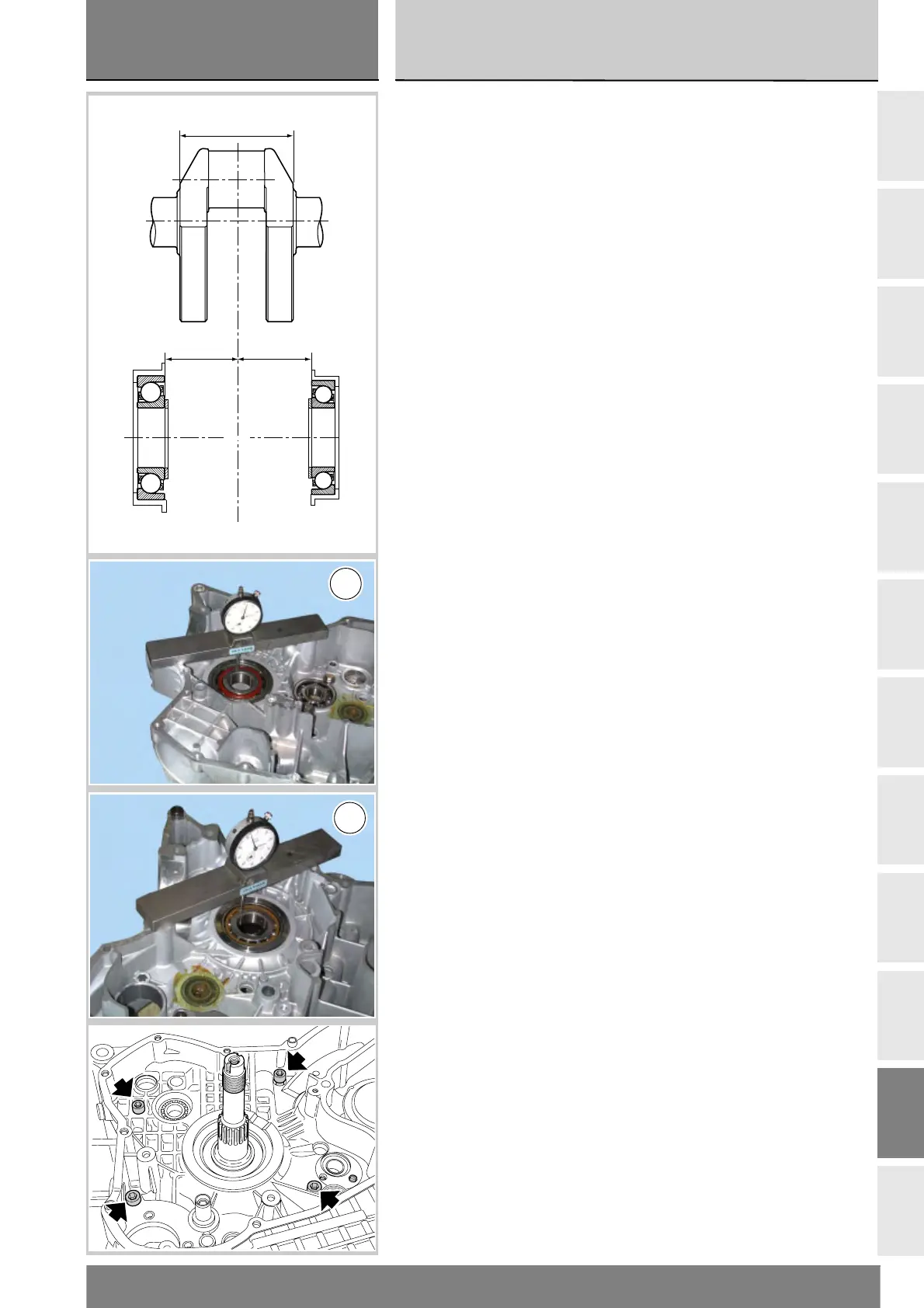
Misurare la quota “LA” tra le superfici
di appoggio dei cuscinetti sull'albero
motore;
Misurare le profondità “LA1” e
“LA2” corrispondenti alla distanza
tra piano di contatto semicarter e
superficie di appoggio della pista
interna dei cuscinetti;
Aggiungere un precarico di 0,30 mm,
per evitare un eccesivo gioco assiale
dell'albero motore quando i
semicarter raggiungeranno la
temperatura di esercizio.
Otterremo così:
SA=LA1+LA2+0,30-LA.
Per calcolare l'entità di una singola
spessorazione è necessario sapere
che:
SA=SA1+SA2
dove “SA1” e “SA2” rappresentano
le spessorazioni relative ai semicarter
lato frizione 1 e lato catena 2.
Considerando l'allineamento
dell'albero otterremo:
SA1=LA1+0,15-LA/2;
Ed infine la seconda spessorazione:
SA2=SA-SA1.
Oltre a quanto riportato, illustriamo
anche una pratica procedura che
permette di determinare correttamente
lo spessore dei rasamenti da montare
sull'albero motore.
Inserire su ogni lato dell'albero motore
un rasamento di spessore minimo
(1,90 mm) per evitare il contatto della
mannaia dell'albero con il basamento.
Installare l'albero motore nel
semicarter e chiudere il basamento.
Montare quattro viti M8 nelle sedi
indicate in figura e bloccarle alla
coppia prescritta (Sez. C 3).
Shimming the shafts
Before closing the casings calculate
the shims required to take up
crankshaft and gearbox shafts
end float.
To determine correct shimming
proceed as follows.
Shimming the crankshaft
After fitting the new main bearings
proceed as follows to determine total
shimming value “SA”:
Measure distance “LA” between the
crankshaft surfaces that contact the
bearings;
Measure depths “LA1” and “LA2”
corresponding to the distance
between the contact surface between
the casings and the contact surface of
the inner race of the bearings;
Add pre-load of 0.30 mm to prevent
excessive end float of the crankshaft
when casings reach their operating
temperature.
This gives:
SA=LA1+LA2+0.30-LA.
To calculate the amount of each
casing shimming note that:
SA=SA1+SA2
where “SA1” and “SA2” represent
the shimming for the clutch side
casing 1 and the chain side casing 2.
Considering shaft alignment, this
gives:
SA1=LA1+0.15-LA/2;
And finally, the second shimming:
SA2=SA-SA1.
In addition to the above description,
the following text illustrates a
practical shimming procedure,
providing a guide on how to calculate
crankshaft shims accurately.
Install a shim of minimum thickness
(1.90 mm) on each side of the
crankshaft to avoid contact between
the crankshaft web and the engine
block.
Fit crankshaft into casing and close
engine block.
Fit four M8 screws into the holes
shown in the figure and tighten to the
specified torque (Sect. C 3).
LA
LA2
LA1
Piano contatto semicarter
Crankcase contact surface
LA1
LA2