A
B
C
D
E
F
G
H
L
M
N
P
Comandi - Dispositivi
Controls - Devices
sezione / section
F 3
17 749/749 DARK/749S - M.Y. 2005 - edizione/edition 00
Attenzione
La casa costruttrice delle pinze
e delle pompe freno, considerando
l’importanza in termini di sicurezza
che rivestono questi componenti,
suggerisce di non intervenire in
nessun modo all’interno della pinza o
della pompa. Una revisione non
eseguita correttamente può mettere
in serio pericolo l’incolumità del pilota
e del passeggero.
Le operazioni di sostituzione si
devono limitare; alla leva di comando,
al gruppo serbatoio con relativi
componenti di fissaggio e al fissaggio
pompa.
Smontaggio pompa freno
idraulico anteriore
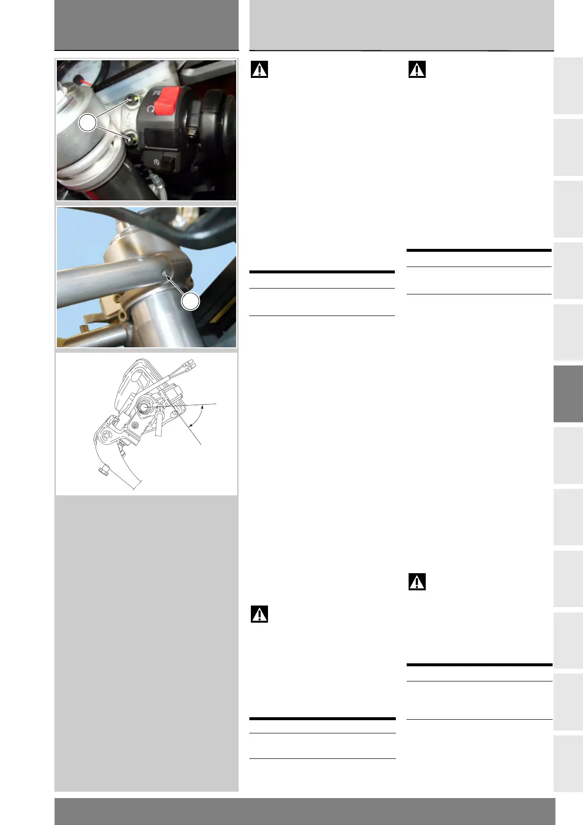
Svitare le viti (1) di fissaggio e
rimuovere il gruppo pompa freno
anteriore dal semimanubrio.
Per lo smontaggio e la sostituzione
dei componenti del gruppo pompa
seguire le indicazioni dell’esploso
riportato a inizio capitolo.
Quando si effettua il rimontaggio delle
tubazioni è necessario interporre i
raccordi con le guarnizioni (4) e serrare
la vite alla coppia prescritta (Sez. C 3).
Rimontaggio pompa
freno idraulico anteriore
Posizionare il perno di riferimento sul
corpo pompa nell’apposito foro (A)
ricavato sul semimanubrio.
Eseguire il serraggio alla coppia
prescritta delle viti (1) procedendo
nella sequenza 1-2-1, partendo
sempre da quella superiore.
Attenzione
Una tubazione mal posizionata
può causare un malfunzionamento
dell’impianto frenante e può
ostacolare le parti in movimento del
motociclo. Rispettare l’orientamento
rappresentato in figura.
Per la sostituzione delle tubazioni
freno anteriore (Sez. G 3).
Operazioni Rif. Sez.
Svuotamento
dell’impianto frenante
D 4
Scollegare il tubo
comando freno dal
gruppo pompa
G 3
Operazioni Rif. Sez.
Ricollegare il tubo
comando freno alla pompa
G 3
Riempimento
dell’impianto frenante
D 4
Warning
Critical safety components.
The brake calliper and master cylinder
manufacturer advises against
servicing the internal components
of calliper and brake master cylinder.
Incorrect overhaul of this critical
safety component can endanger
rider and passenger safety.
Maintenance operations on these
units are limited to replacing the
following parts: control lever,
reservoir unit, reservoir fasteners and
master cylinder fasteners.
Removing the front brake
master cylinder
Undo retaining screws (1) and then
remove the front brake master
cylinder from the handlebar.
Refer to the exploded view at the
beginning of this section for
indications on disassembly and
replacement of the brake unit
components.
When refitting the hoses, install the
fittings with their gaskets (4) and lock
down the screw to the prescribed
torque (Sect. C 3).
Refitting the front brake
master cylinder
Locate the pin on the cylinder body in
the hole (A) in the handlebar.
Tighten the screws (1) to the
prescribed torque in a 1-2-1 sequence,
always starting with the top screw.
Warning
If incorrectly positioned, the
hose can affect brake operation
and interfere with moving parts.
Arrange as shown in the figure.
For renewal of front brake hoses, see
Sect. G 3.
Operation See Sect.
Draining the brake
circuit
D 4
Disconnect the brake
hose from the master
cylinder unit
G 3
Operation See Sect.
Reconnect the brake
hose to the master
cylinder unit
G 3
Filling the brake circuit D 4
1
A
65˚±2