A
B
C
D
E
F
G
H
L
M
N
P
Motore
Engine
sezione / section
N 4.4
80 749/749 DARK/749S - M.Y. 2005 - edizione/edition 00
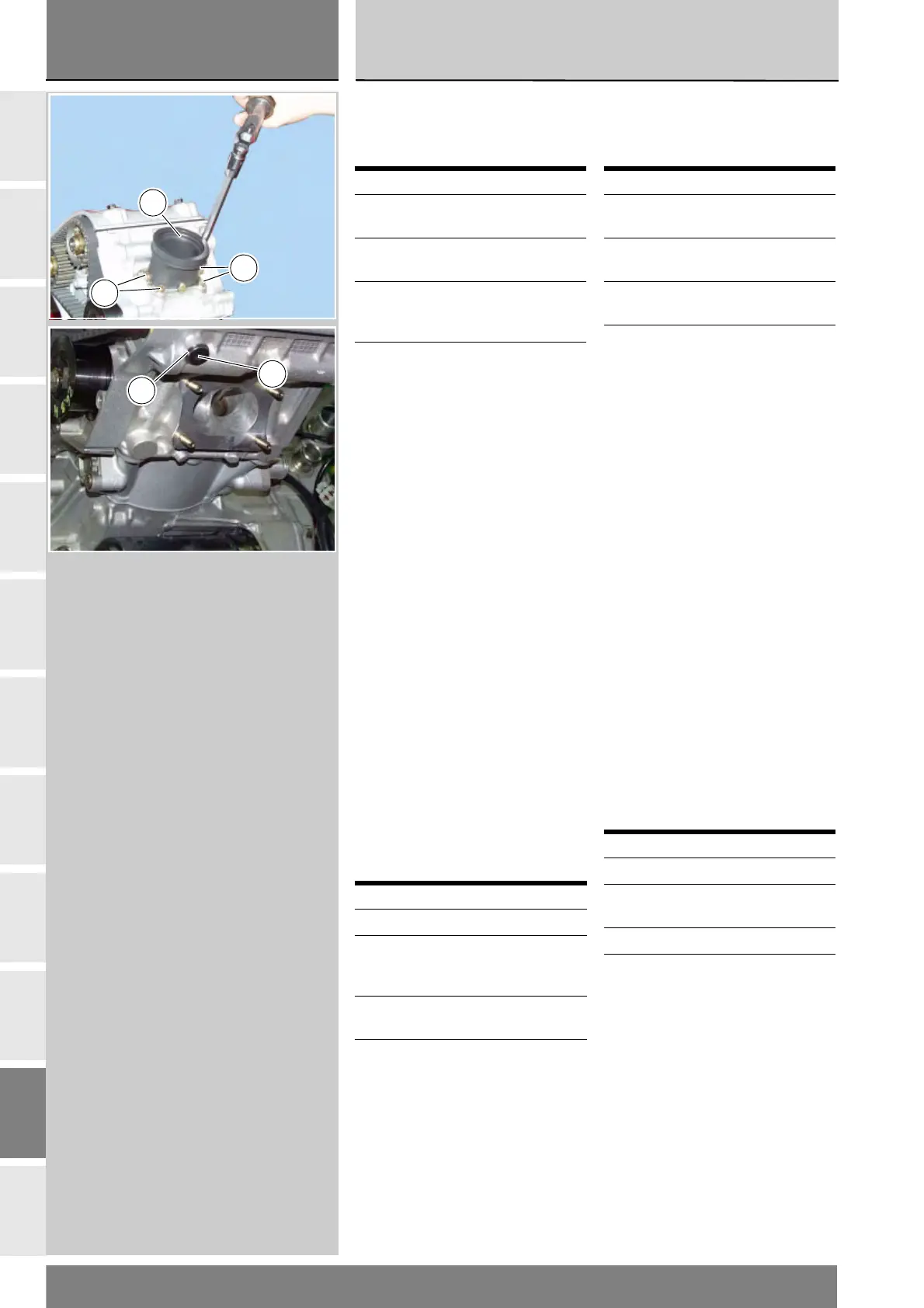
Smontaggio collettore
aspirazione e tappo foro
mandata olio
Rimuovere i collettori (25), svitando
le viti (21).
Svitare la vite (4) per ispezionare il
foro mandata olio, recuperando la
guarnizione (5).
Rimontaggio collettore
aspirazione e tappo foro
mandata olio
Dopo aver verificato che le superfici di
contatto sulla testa e sul collettore
risultino perfettamente piane e pulite,
installare il collettore di aspirazione (25)
sulla testa.
Bloccare le quattro viti (21) di fissaggio
alla coppia di serraggio prescritta
(Sez. C 3), operando a croce.
Tappare il foro di mandata olio di
lubrificazione sul lato scarico della
testa con la vite (4) e relativa
guarnizione (5).
Bloccare la vite (4) alla coppia
prescritta (Sez. C 3).
Operazioni Rif. Sez.
Rimuovere le carene
laterali
E 2
Rimuovere il radiatore
acqua
N 3.2
Rimuovere il gruppo
codone-serbatoio
benzina
E 3
Rimuovere l’airbox L 6
Operazioni Rif. Sez.
Rimontare l’airbox L 6
Rimontare il gruppo
codone-serbatoio
benzina
E 3
Rimontare il radiatore
acqua
N 3.2
Rimontare le carenature
laterali
E 2
Removing the intake
manifold and oil delivery
hole plug
Remove the manifolds (25) by
undoing screws (21).
Undo the screw (4) to inspect the
oil delivery hole and recover the
gasket (5).
Reinstalling the intake
manifold and oil delivery
hole plug
Check that the mating surfaces of the
head and manifold are perfectly flat
and clean and install the intake
manifold (25) to the head.
Tighten the four screws (21) to the
specified torque (Sect. C 3), working
crossways.
Plug the oil delivery hole on the head
exhaust side with screw (4) and its
gasket (5).
Tighten screw (4) to the specified
torque (Sect. C 3).
Operation See Sect.
Remove the side
fairings
E 2
Remove the water
cooler
N 3.2
Remove the fuel tank/
rear fairing assembly
E 3
Remove the airbox L 6
Operation See Sect.
Refit the airbox L 6
Refit the fuel tank/rear
fairing assembly
E 3
Refit the water cooler N 3.2
Refit the side fairings E 2
21
21
25
5
4