A
B
C
D
E
F
G
H
L
M
N
P
Motore
Engine
sezione / section
N 9.3
181 749/749 DARK/749S - M.Y. 2005 - edizione/edition 00
Ricomposizione
imbiellaggio
Verificare prima del montaggio che i
perni di banco e di biella sull'albero
motore non presentino bavature o
segni evidenti di lavoro: eventualmente
riprendere le superfici con tela
finissima e olio.
Verificare che le scanalature risultino
integre, senza segni di forzature.
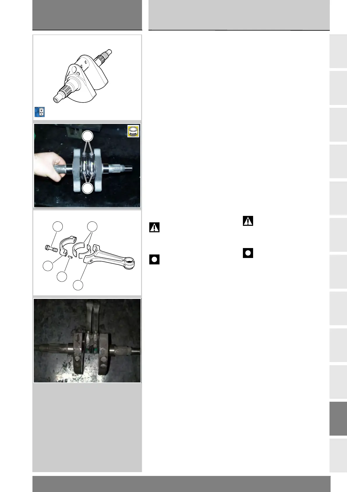
Verificare che su ogni biella (2), tra
cappello e il relativo fusto, siano
montate le spine di centraggio (D).
Provvedere al lavaggio e all'asciugatura
delle spine con aria compressa.
Pulire e lubrificare con olio motore il
perno di biella e i semicuscinetti (3)
quindi montare le bielle sull'albero
motore, nella stessa posizione in cui
sono state rimosse.
Lubrificare con grasso prescritto il
filetto e il sottotesta delle viti (1)
nuove e la sede filettata sul fusto,
introducendo grasso dalle due
estremità del foro.
Attenzione
Il grasso utilizzato è irritante al
contatto con la pelle; indossare guanti
protettivi.
Importante
La lubrificazione delle viti di
biella è fondamentale per ottenere
l'accoppiamento prescritto ed evitare
la rottura dei componenti.
Le viti biella possono essere utilizzate
solo per tre serraggi.
Avvitare a mano le viti (1) fino a battuta.
Se l'operazione risulta difficoltosa o si
riscontrano impuntamenti, svitare la
vite e lubrificare nuovamente.
Rimuovere l'eccesso di grasso.
Accostare a mano la vite fino al
contatto tra la testa della vite ed il
piano d'appoggio sulla biella.
Interporre tra le bielle il distanziale
88713.1309 ed eliminare il gioco
assiale residuo inserendo lo
spessimetro a forchetta 88765.1000
disponibile negli spessori:
0,1 mm (88765.1000) - 0,2 mm
(88765.1005) - 0,3 mm (88765.1006).
Montare provvisoriamente lo spinotto
per pistone, per allineare le bielle,
quindi procedere al serraggio.
Reassembling the
connecting rods
Before starting the work check that
the crankshaft main journals and the
crank pins are free of burr or evident
signs of working: if necessary clean
the surfaces with very fine emery
cloth and oil.
Check that the grooves are in perfect
condition with no signs of shrinkage.
Check that each connecting rod (2)
and cap are equipped with their
locating pins (D).
Wash the pins and dry them with
compressed air.
Clean and lubricate crank pin and con-
rod bearings (3) with engine oil and fit
the con-rods in their original mounting
positions.
Use the recommended grease to
lubricate the threads and underside of
the heads of the new bolts (1) and the
threaded hole in the con-rod, packing
in grease from both ends of the hole.
Warning
The grease utilised is an irritant
in contact with the skin. Wear
protective gloves.
Important
Lubrication of con-rod bolts is
essential to obtain the correct coupling
and prevent breakage of the parts.
Only use the same con-rod screws
three times.
Snug the bolts (1) fully home by hand.
If this proves difficult or in the case of
jamming, undo the bolts and lubricate
them again.
Remove excess grease. Snug the bolt
by hand until the bolt head locates
against the con-rod surface.
Fit spacer part no. 88713.1309
between the connecting rods and
take up residual axial play by inserting
fork feeler gauge 88765.1000 which
is available in the following
thicknesses:
0.1 mm (88765.1000) - 0.2 mm
(88765.1005) - 0.3 mm (88765.1006).
Temporarily fit the gudgeon pin to
align the connecting rods, and then
tighten the bolts.
B
1
1
1 3
2
D
2