A
B
C
D
E
F
G
H
L
M
N
P
Ruote - Sospensioni - Freni
Wheels - Suspensions - Brakes
sezione / section
G 3
21 749/749 DARK/749S - M.Y. 2005 - edizione/edition 00
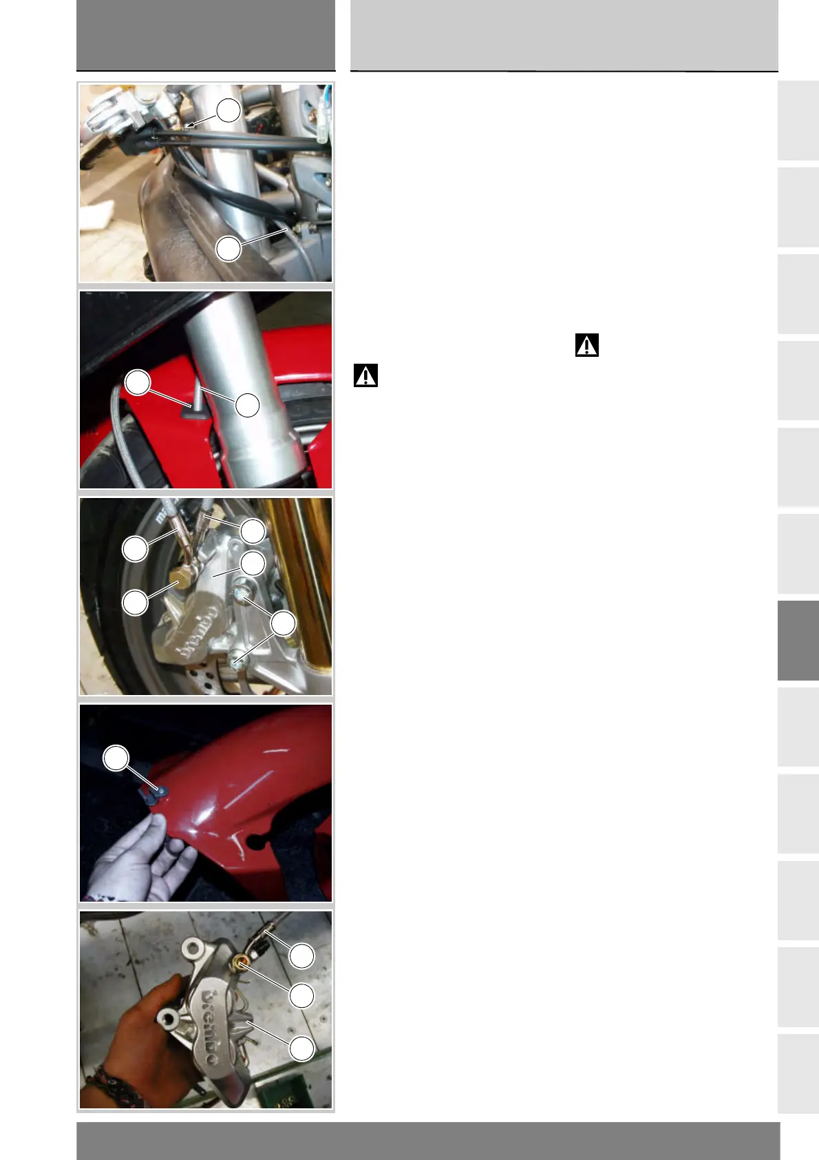
Smontaggio impianto
freno anteriore
Prima di procedere alla separazione
dei componenti dell’impianto occorre
eseguire lo svuotamento del circuito
(Sez. D 4).
Smontaggio pinze freno
anteriori
Svitare la vite speciale (2) di fissaggio
tubo freno alla pompa recuperando
le guarnizioni (1).
Sfilare la tubazione (3), dal
gommino (20) sul parafango e
sganciare la tubazione (7) dalla
graffetta (18).
Attenzione
Se durante la rimozione della
tubazione freno anteriore viene
danneggiata la graffetta (18) è
necessario sostituirla (Sez. E 4).
Il tubo senza il ritegno prodotto dalla
graffetta può, in fase di frenata, venire
a contatto con il pneumatico e
causare incidenti.
Rimuovere la pompa freno (Sez. F 3).
Svitare le viti (5) di fissaggio pinza
freno anteriore destra (8) allo stelo
forcella.
Eseguire la stessa operazione per
la pinza freno sinistra (9).
Rimuovere le due pinze freno (8) e (9)
complete di tubazione.
Svitare le viti (6) e (2) sulle rispettive
pinze freno per separarle dalle
tubazioni (3) e (7).
Removing the front brake
system
Before disassembling the system
components, drain the circuit
(Sect. D 4).
Removing the front brake
callipers
Undo special screw (2) securing the
brake hose to the master cylinder and
recover the gaskets (1).
Remove the hose (3) from the
grommet (20) on the mudguard and
release hose (7) from clip (18).
Warning
If the clip (18) is damaged while
removing the front brake hose,
it must be replaced (Sect. E 4).
In the absence of the restraint
provided by the clip the brake hose
could come into contact with the tyre
during braking and thus lead to
accidents.
Remove the brake master cylinder
(Sect. F 3).
Undo the screws (5) securing the RH
front brake calliper (8) to the fork leg.
Repeat the operation for the LH brake
calliper (9).
Remove the two brake callipers (8)
and (9) complete with their hoses.
Unscrew the screws (6) and (2) on the
brake callipers so as to separate them
from the hoses (3) and (7).
2
3
3
20
7
6
3
8
5
18
7
2
9