A
B
C
D
E
F
G
H
L
M
N
P
Mototelaio
Frame
sezione / section
H 5
18 749/749 DARK/749S - M.Y. 2005 - edizione/edition 00
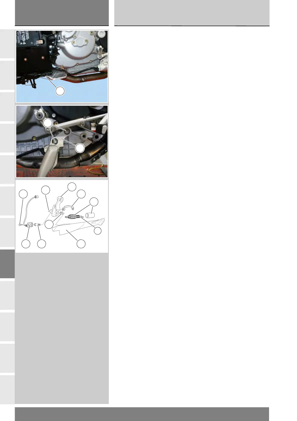
Smontaggio cavalletto
laterale
Rimuovere la carena sinistra (Sez. E 2).
Scollegare il connettore (A)
dell’interruttore cavalletto (3)
dal cablaggio principale.
Svitare le due viti (9) di fissaggio della
piastra (10) di supporto cavalletto al
motore e rimuovere il cavalletto
laterale completo.
Scomposizione cavalletto
laterale
Svitare la vite (1) di fissaggio e
rimuovere l’interruttore (3) del
cavalletto.
Sganciare le molle (7) e (8), di ritorno
cavalletto, dal perno posizionato sulla
piastra supporto cavalletto (10), e
rimuoverle.
Svitare il perno (2) di fissaggio
cavalletto alla piastra e rimuovere la
stampella laterale (5).
Ispezione cavalletto laterale
Verificare, introducendo la stampella
nella piastra, che non vi sia gioco
eccessivo e che le due estremità della
stampella non risultino piegate
rispetto al fusto.
Individuando segni di frattura,
sostituire il cavalletto.
Per la verifica dell’interruttore (3)
consultare la Sezione P 6.
Removing the side stand
Remove the LH side fairing (Sect. E 2).
Disconnect connector (A) of stand
switch (3) from the main wiring
harness.
Undo the two screws (9) securing
stand plate (10) to the engine and
remove the complete side stand.
Disassembling the side
stand
Unscrew retaining screw (1) and
remove stand switch (3).
Release the stand return springs (7)
and (8) from the stand plate pivot (10),
and remove them.
Unscrew the pivot (2) securing the
stand to the plate and remove the
side leg (5).
Inspecting the side stand
Fit the stand leg to the plate and
check that there is no excessive play.
Ensure that the ends of the stand leg
are not bent with respect to the shank.
A stand which shows signs of
cracking must be replaced
immediately.
See Section P 6 for testing the
switch (3).
A
10
9
10
8
1
B
6
7
3 2 5
4