A
B
C
D
E
F
G
H
L
M
N
P
Impianto iniezione - accensione
Ignition - injection system
sezione / section
M 3
17 749/749 DARK/749S Aggiornamento/Update - M.Y. 2006 - edizione/edition 00
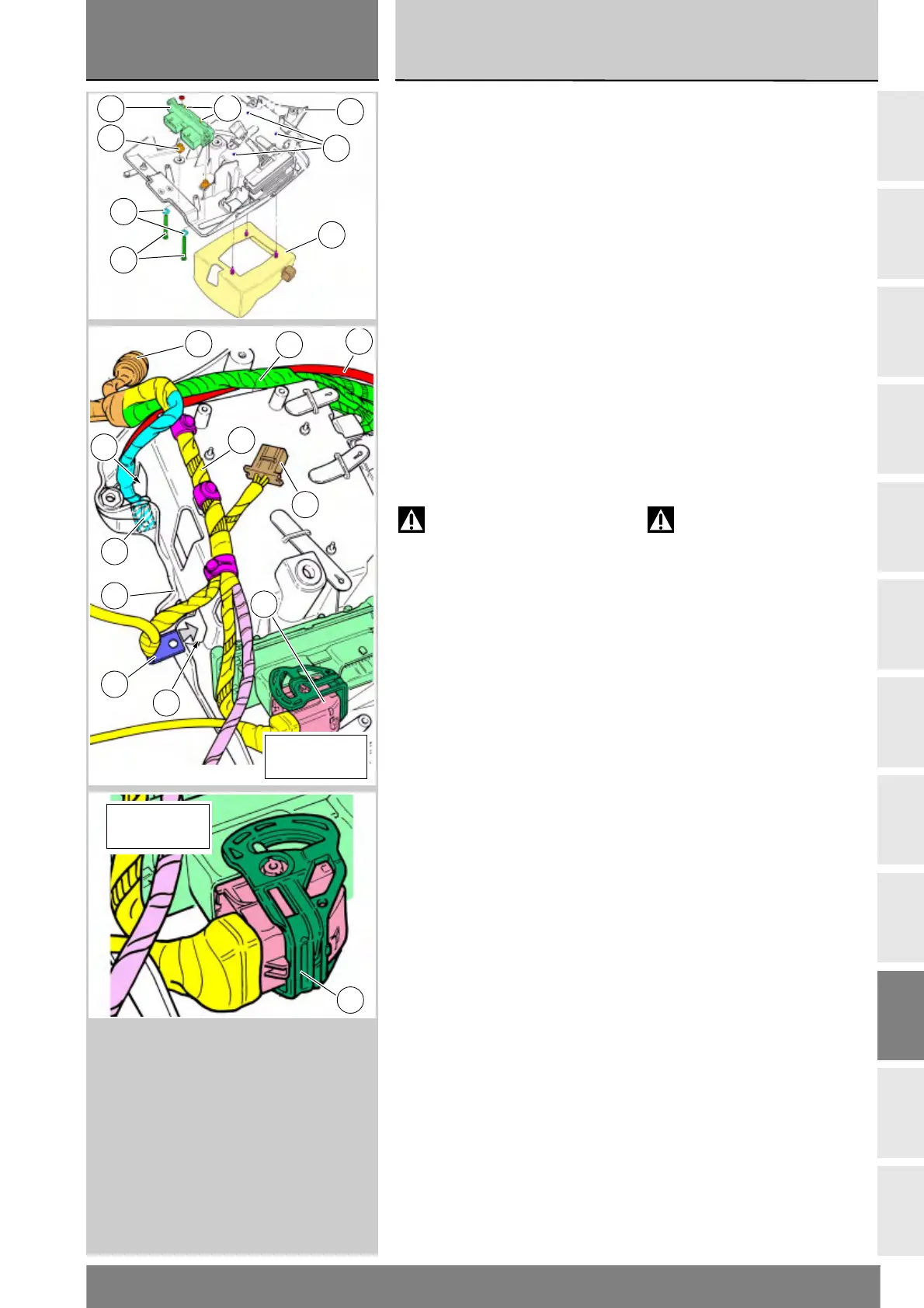
Rimontaggio supporto
batteria
Controllare lo stato di tutte le parti in
gomma ed eventualmente sostituirle.
Se è stato rimosso montare il
tappetino batteria (32) all'interno
della propria sede infilando i pioli negli
appositi fori (C) sul supporto batteria.
Introdurre la parte con diametro
minore dei distanziali (26) negli
appositi gommini.
Montare la centralina (25) orientandola
con i pioli (D) rivolti verso l'alto,
inserendo le viti (31) e le rosette (33)
ed impuntare il dado (24) di sinistra.
Stendere il cablaggio (34) inserendo
il terminale (E) nella sede (F) del
supporto batteria (2).
Cablare il ramo principale lato
sinistro (G) con le relative fascette
come mostra la figura.
Attenzione
Il cavo teleruttore (H) deve
seguire il profilo superiore del
supporto batteria passando sotto
al ramo principale lato destro (I).
Il ramo principale lato destro (I)
deve passare sotto al ramo
principale lato sinistro (G).
Verificare che il connettore per
regolatore (13) sia rivolto verso
l'interno del supporto batteria.
Inserire il terminale (L) del cavo
negativo batteria nella sede (M).
Verificare che la guida di sicurezza del
connettore (22) della centralina (25) sia
in posizione “Aperta” come mostra la
figura.
Inserire in asse fino a battuta, il
connettore nella centralina (25) e
ruotare la guida in posizione “Chiusa”
come mostra la figura.
Refitting the battery
mount
Check the condition of all rubber
components and replace them if
necessary.
If it has been removed, refit the
battery underlay (32) in its seat,
locating the pins in the holes (C)
on the battery mount.
Insert the small diameter side of
the spacers (26) into their rubbers.
Mount the ECU (25) with the pins (D)
uppermost, fitting the screws (31)
and washers (33) and starting the LH
nut (24).
Lay out the cabling (34) and fit
terminal (E) into its seat (F) in the
battery mount (2).
Position the LH side wiring harness
(G) and secure it with clips as shown
in the diagram.
Warning
The contactor cable (H) must
follow the upper profile of the battery
mount, passing under the RH side
wiring harness (I).
The RH side wiring harness (I) must
pass under the LH side wiring
harness (G).
Check that the regulator connector (13)
is facing the inside of the battery
mount.
Fit the terminal (L) of the battery
negative cable into its seat (M).
Check that the safety slide for
connector (22) of the ECU (25) is in
the “Open” position as shown in
the figure.
Insert the connector fully into the
ECU (25) and rotate the slide into the
“Closed” position as shown in the
figure.
C
D
33
31
26
25
32
2
34
G
I
13
E
2
L
22
H
F
M
Guida aperta
Slide open
22
Guida chiusa
Slide closed