A
B
C
D
E
F
G
H
L
M
N
P
Impianto iniezione - accensione
Ignition - injection system
sezione / section
M 3
18 749/749 DARK/749S Aggiornamento/Update - M.Y. 2006 - edizione/edition 00
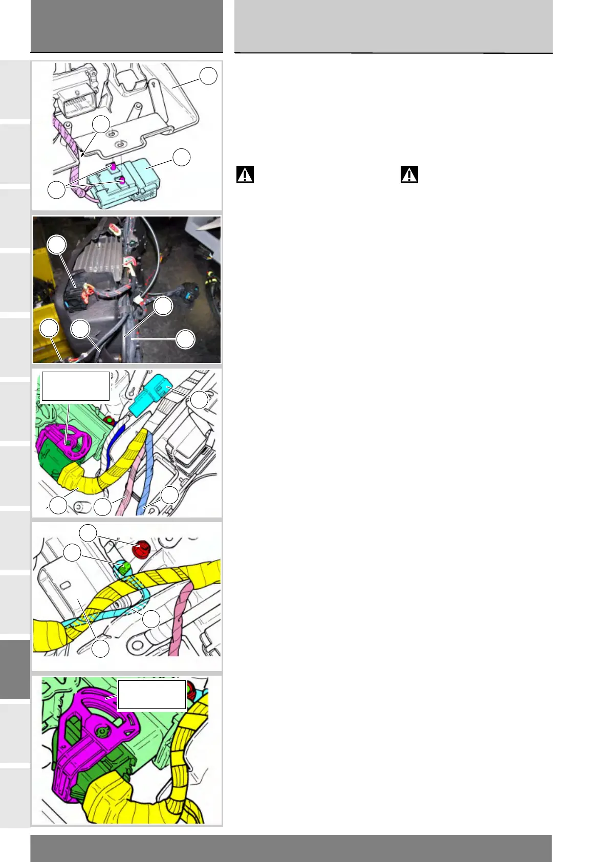
Montare il fusibile regolatore (30)
posizionando il cavo all'interno del
relativo scasso (N), inserendo i pioli (B)
nei rispettivi fori del supporto batteria (2).
Cablare il ramo principale destro (I) ed
il cavo teleruttore (H) con le relative
fascette come mostra la figura.
Attenzione
Il cavo teleruttore (H) deve
passare alla destra del ramo
principale destro (I).
I cavi ventola (O) ed il cavo acqua (P)
devono rimanere liberi.
Montare la fusibiliera (27) inserendola
nel supporto batteria.
Posizionare il cavo connettore per
centralina (23), il cavo bobina (R), il
connettore per teleruttore (14) ed il
cavo (35) come mostra la figura.
Inserire il cavo di massa centralina (S)
sulla vite (31) impuntando il dado (24).
Verificare la guida del connettore (23)
che sia in posizione “Aperta” ed
inserirlo a battuta nella centralina.
Ruotare la guida fino al bloccaggio del
connettore in posizione “Chiusa”.
Serrare alla coppia prescritta (Sez. C 3)
i dadi (24) che fissano la centralina (25).
Fit the regulator fuse (30) with the
cable inside the slot (N), locating the
pins (B) in their respective holes in
the battery mount (2).
Run the RH side wiring harness (I) and
contactor cable (H) and secure them
with clips as shown in the diagram.
Warning
The contactor cable (H) must
pass to the right of the RH wiring
harness (I).
The fan (O) and coolant (P) cables
must remain free.
Install the fuse block (27) in the
battery mount.
Position the ECU cable connector (23),
coil cable (R), contactor connector (14)
and cable (35) as shown in the figure.
Fit the ECU ground wire (S) to the
screw (31) and fit the nut (24).
Make sure the slide for connector (23)
is “Open” and plug the connector
into the ECU.
Rotate the slide until it locks the
connector in the “Closed” position.
Tighten the nuts (24) securing the
ECU (25) to the specified torque
(Sect. C 3).
2
N
B
30
O
P
27
I
H
Guida aperta
Slide open
14
23
R
35
S
24
31
25
Guida chiusa
Slide closed