A
B
C
D
E
F
G
H
L
M
N
P
Mototelaio
Frame
sezione / section
H 2
8 749/749 DARK/749S Aggiornamento/Update - M.Y. 2006 - edizione/edition 00
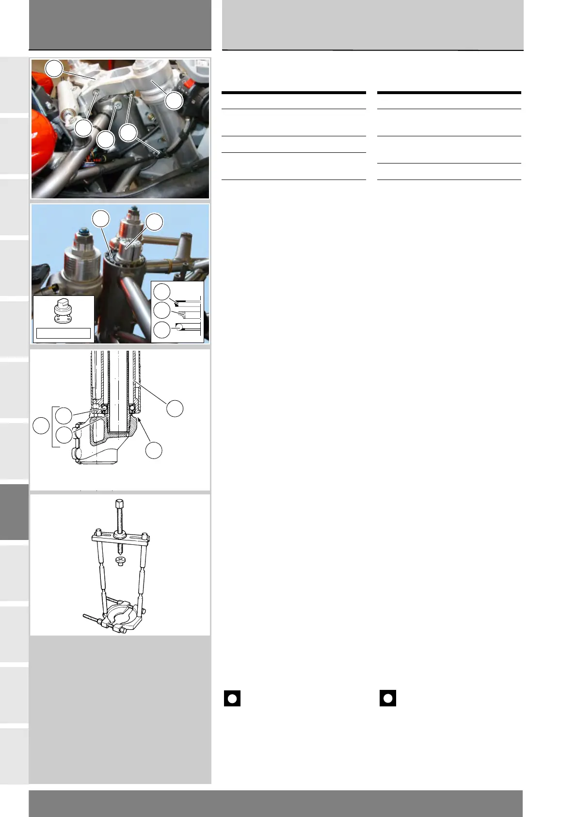
Smontaggio componenti
cannotto di sterzo
Allentare la vite (5) che blocca la testa
di sterzo sulla ghiera (10). Allentando
la vite (5) si libera il martelletto del
bloccasterzo. Segnare la posizione
del martelletto perchè al rimontaggio
dovrà essere in posizione originale.
Sfilare la testa di sterzo (11).
Con l'attrezzo cod. 88713.1058
allentare la ghiera (10) e svitarla dal
perno di sterzo.
Sfilare dal perno di sterzo l'anello di
tenuta (2), la pista interna (C) e la
corona di sfere (B) del cuscinetto (3)
superiore.
Per agevolare l’operazione, battere il
perno di sterzo per poi riuscire a
scalzare i componenti citati.
Rimuovere i seeger (8) e allentare le
viti (7). Svitare e rimuovere la vite (9)
che definisce la posizione dell'angolo
di sterzo (Segnarsi la posizione per
riposizionarla durante il rimontaggio).
749S
Sfilare dal tubo del telaio il cannotto
(4) con perno e base di sterzo.
Supportare il cannotto (4) e con
mazzuolo battere sul perno per sfilarlo
unitamente alla base di sterzo (1).
749/749 DARK
Sfilare dal tubo del telaio la base di
sterzo (1) completa di perno.
Sfilare la corona di sfere (B) del
cuscinetto inferiore (3).
Sul perno rimarrà posizionata la pista
interna (C) del cuscinetto inferiore e il
relativo anello di tenuta (2).
Utilizzare un estrattore universale
(del tipo raffigurato) per rimuovere la
pista (C) dal perno di sterzo, facendo
molta attenzione a non rovinare la sede.
Importante
Gli anelli di tenuta (2) e i
cuscinetti (3) rimossi non vanno più
rimontati.
Rimuovere gli anelli esterni dei
cuscinetti dal cannotto utilizzando un
punzone adeguato e facendo molta
attenzione a non rovinare le sedi.
Operazioni Rif Sez.
Rimuovere le
carenature laterali
E 2
Rimuovere il cupolino E 1
Rimuovere gli steli
forcella
G 2
Rimuovere
l'ammortizzatore di
sterzo 749/749S
H 3
Removing the steering
tube components
Loosen the screw (5) securing the top
yoke to the ringnut (10). Slackening
off the screw (5) frees the steering
lock peg. Mark the position of the peg
to ensure that it is replaced in its
original position on reassembly.
Remove the top yoke (11).
Using tool part no. 88713.1058
loosen the ring nut (10) and remove
it from the steering stem.
Remove the seal (2), inner ring (C)
and ball race (B) of the upper bearing
from the steering stem.
Tap the the stem to dislodge the
above components.
Remove the circlips (8) and slacken
off the screws (7). Unscrew and
remove the screw (9) which sets the
steering angle (mark its position to
refit it correctly during reassembly).
(749S)
Extract the steering tube (4) with the
stem and bottom yoke from the
frame tube.
Support the steering tube (4) and
tap the stem with a mallet to drive
it out pf the tube along with the
bottom yoke (1).
749/749 DARK
Remove the bottom yoke (1) complete
with the stem from the frame tube.
Remove the ball race (B) of the
lower bearing (3).
The inner race (C) of the lower
bearing and its seal ring (2) will
remain on the stem.
Using a universal puller (of the type
shown in the figure) remove the ring
(C) from the steering stem, taking
care not to damage the seat.
Important
Once removed, the seals (2)
and bearings (3) must not be refitted.
Using a suitable drift, remove the
outer bearing races from the steering
tube. Proceed with extreme care to
avoid damaging the seats.
Operation See Sect.
Remove the side
fairings
E 2
Remove the headlight
fairing
E 1
Remove the fork legs G 2
Remove the steering
damper 749/749S
H 3
11
10
5
9
7
88713.1058
10
2
C
B
4
4
2
B
C
3