A
B
C
D
E
F
G
H
L
M
N
P
Ruote - Sospensioni - Freni
Wheels - Suspensions - Brakes
sezione / section
G 3
24 749/749 DARK/749S - M.Y. 2005 - edizione/edition 00
Note
Fare attenzione che sulla pinza
freno destra (8) siano montati il
raccordo della tubazione (7) all’interno
e il raccordo della tubazione (3)
all’esterno.
Inserire la pinza freno destra (8) sul
disco.
Posizionare la tubazione (3) all’interno
del gommino (20) e montarlo
nell’apposita asola sul parafango.
Applicare grasso prescritto nelle viti (5)
e serrarle alla coppia prescritta
(Sez. C 3).
Eseguire la stessa operazione per il
montaggio della pinza freno destra (9).
Posizionare il gruppo pompa/leva
(Sez. F 3).
Inserire la tubazione freno
anteriore (7) nella graffetta (18)
posizionata sul parafango anteriore.
Eseguire il riempimento dell’impianto
(Sez. D 4).
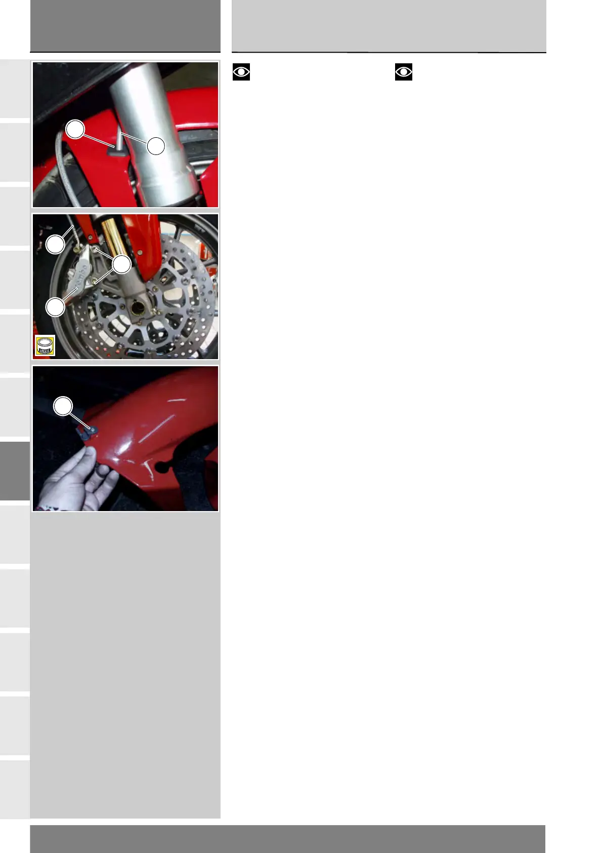
Notes
Make sure that internal hose
fitting (7) and external hose fitting (3)
are installed on the RH brake
calliper (8).
Fit the RH brake calliper (8) on the disc.
Locate the hose (3) through the
grommet (20) and mount the hose in
the slot in the mudguard.
Apply the prescribed grease to
screws (5) and tighten to the
prescribed torque (Sect. C 3).
Repeat the operation to refit the RH
brake calliper (9).
Position the brake master cylinder-
lever assembly (Sect. F 3).
Fit the front brake hose (7) into the
clip (18) on the front mudguard.
Fill the brake circuit (Sect. D 4).
3
20
5
8
3
B
18