A
B
C
D
E
F
G
H
L
M
N
P
Impianto iniezione - accensione
Ignition - injection system
sezione / section
M 2
11 749/749 DARK/749S Aggiornamento/Update - M.Y. 2006 - edizione/edition 00
Legenda schema impianto
iniezione - accensione
1 Commutatore chiave
2 Elettroventola sinistra
3 Elettroventola destra
4 Motorino avviamento
5 Teleruttore avviamento
6 Batteria
7 Serbatoio
8 Autodiagnosi
9 Fusibili iniezione
10 Relè iniezione
11 Bobina cilindro orizzontale
12 Bobina cilindro verticale
13 Candela cilindro orizzontale
14 Candela cilindro verticale
15 Iniettore cilindro orizzontale
16 Iniettore cilindro verticale
17 Potenziometro farfalla
18 Sensore giri/fase
19 Sensore temperatura acqua
20 Sensore velocità
21 Stampella laterale
22 Sensore folle
23 Interuttore pressione olio
24 Centralina iniezione
25 Fusibile Key On
26 Sensore temperatura aria
27 Strumentazione
Codici colore cavi schema
iniezione - accensione
B Blu
W Bianco
V Viola
Bk Nero
Y Giallo
R Rosso
Lb Azzurro
Gr Grigio
G Verde
Bn Marrone
O Arancio
P Rosa
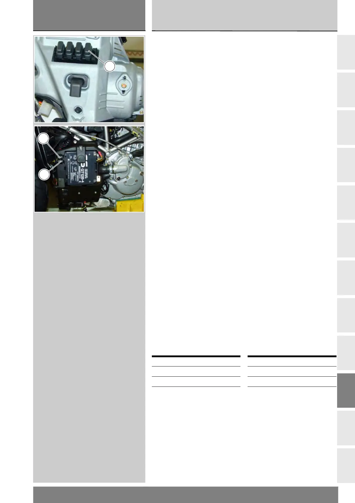
Legenda scatola fusibili
impianto iniezione - accensione
Per il controllo dei fusibili (Sez. P 6).
Pos. Utilizzatori Val.
A Key sense 7,5 A
B Centralina 3 A
C Relè iniezione 20 A
Key to the injection –
ignition diagram
1 Key switch
2 Left electric fan
3 Right electric fan
4 Starter motor
5 Starter contactor
6 Battery
7 Fuel tank
8 Self-diagnosis
9 Injection fuses
10 Injection relay
11 Horizontal cylinder coil
12 Vertical cylinder coil
13 Horizontal cylinder spark plug
14 Vertical cylinder spark plug
15 Horizontal cylinder injector
16 Vertical cylinder injector
17 Throttle position sensor
18 Rpm/timing sensor
19 Coolant temperature sensor
20 Speed sensor
21 Side stand
22 Neutral sensor
23 Oil pressure switch
24 Injection ECU
25 Key on fuse
26 Air temperature sensor
27 Instruments
Injection - ignition diagram
wiring colour codes
B Blue
W White
V Violet
Bk Black
Y Yellow
R Red
Lb Light blue
Gr Grey
G Green
Bn Brown
O Orange
P Pink
Key to the injection –
ignition fuse box diagram
For fuses check (Sect. P 6).
Pos. Users Val.
A Key sense 7.5 A
B Engine control unit 3 A
C Injection relay 20 A
A
B
C