A
B
C
D
E
F
G
H
L
M
N
P
Motore
Engine
sezione / section
N 4.5
93 749/749 DARK/749S - M.Y. 2005 - edizione/edition 00
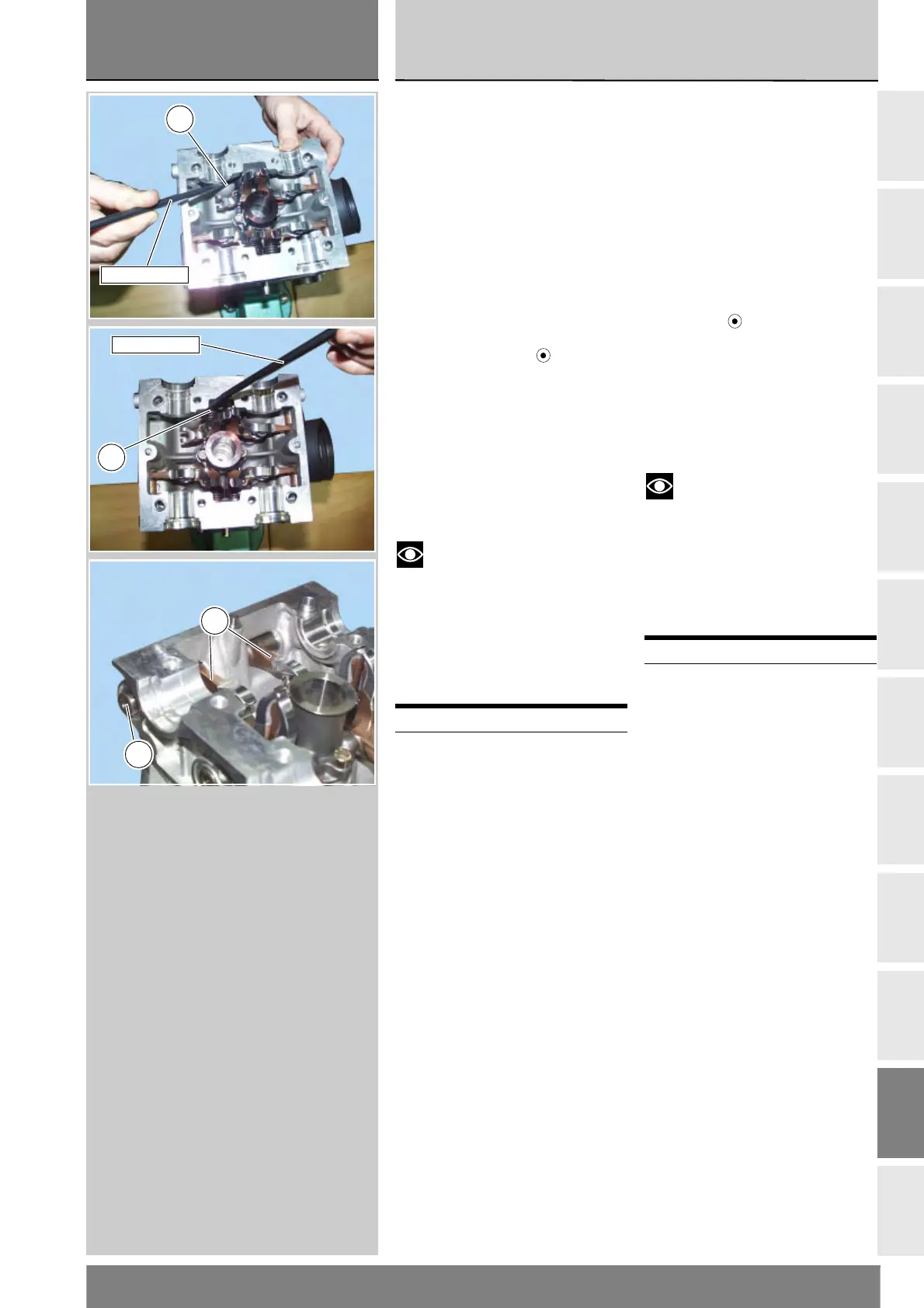
Ruotare fino alla posizione di fermo
l'estremità della molla (19). Verificare,
dopo aver sfilato l'asta forata (D),
che l'estremità della molla risulti
correttamente posizionata
nell'apposita spalla della testa.
Eseguire la stessa operazione per il
bilanciere opposto.
Procedere al rimontaggio dei bilancieri
di apertura (3) e dei relativi perni (2) sul
lato aspirazione e successivamente
dei perni (17) sul lato scarico.
Verificare che il numero stampigliato
“1” o la punzonatura “ ” sulla
faccia esterna del perno bilanciere
(vedi “Smontaggio bilancieri valvola”
di questo capitolo) corrisponda al
montaggio sul bilanciere di apertura
aspirazione, quindi lubrificarlo con olio
motore.
Inserire il perno dall'esterno fino in
battuta sul supporto di ritegno
interno.
Note
Il perno deve sporgere
dalla superficie laterale della testa:
in questo modo assolve alla funzione
di centraggio per le cartelle laterali
della testa.
Eseguire la stessa operazione per il
montaggio del bilanciere opposto.
Operazioni Rif. Sez.
Rimontare la testa
completa sul blocco
motore
N 4.5
Turn the end of the spring (19) until it
stops. Remove the bored shaft (D)
and check that the end of the spring is
positioned in the shoulder of the head.
Repeat the procedure for the
opposite side rocker arm.
Refit the opening rocker arms (3) and
shafts (2) on the intake side and then
refit the shafts (17) on the exhaust
side.
Check that the stamped number “1”
or punching “ ” on the outer face of
the rocker arm shaft (see “Removing
the valve rocker arms” in this chapter)
corresponds to the assembly mark on
the intake closing rocker arm, and
lubricate with engine oil.
Fit the shaft from the outside so that
it seats against the internal retainer.
Notes
The shaft must protrude
from the side surface of the head:
this enables it to act as a centring
element for the side outer covers
of the head.
Repeat the procedure to install the
opposite side rocker arm.
Operation See Sect.
Refit the complete head
on the engine block
N 4.5
19
88713.2069
88713.2069
19
17
3