A
B
C
D
E
F
G
H
L
M
N
P
Motore
Engine
sezione / section
N 5
106 749/749 DARK/749S Aggiornamento/Update - M.Y. 2006 - edizione/edition 00
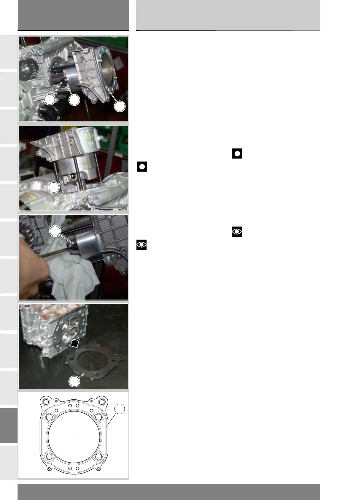
Portare il piede di biella vicino al punto
morto superiore e inserire il gruppo
pistone-cilindro (1-10) nei prigionieri
del carter.
Portare il piede di biella all'interno del
pistone in corrispondenza del foro
dello spinotto (3) ed inserire
quest'ultimo dopo averlo lubrificato.
Lo spinotto deve essere libero di
scorrere nella boccola del piede di
biella e nel pistone (1).
Chiudere l'apertura del carter con uno
straccio per impedire che qualcosa
possa cadere all'interno, quindi
inserire l'anello di fermo (2).
Per il montaggio dell’anello utilizzare
l’attrezzo cod. 88713.2569.
Importante
Utilizzare ad ogni montaggio
anelli di fermo (2) nuovi.
Spingere il cilindro (10) in basso a
contatto con la base del carter.
Inserire la guarnizione (11) testa cilindro
nei prigionieri. Il lato della guarnizione
dove è presente il codice, deve essere
messo a contatto con la testa.
Note
La particolare forma
impedisce il montaggio errato della
guarnizione, a condizione che i fori di
passaggio liquido corrispondano a
quelli presenti sul cilindro.
Eseguire le stesse operazioni per
l'altro cilindro e procedere al
montaggio delle teste (Sez. N 4.5).
Bring the connecting rod small end
close to TDC and slide the cylinder-
piston assembly (1-10) onto the
crankcase studs.
Push the connecting rod small end
into the piston close to the gudgeon
pin (3) bore. Lubricate and insert the
gudgeon pin. The gudgeon pin must
slide smoothly in the connecting rod
small end bush and in the piston (1).
Block off the crankcase opening with a
cloth to prevent foreign objects from
falling inside and then fit circlip (2).
To install the circlip, use special tool
part no. 88713.2569.
Important
Always use two new circlips (2)
on reassembly.
Press the cylinder (10) down until it
stops against the crankcase.
Fit the cylinder head gasket (11)
over the studs. The side marked
with the part no. must be placed in
contact with the head.
Notes
The shape prevents incorrect
fitting of the gasket, provided that
the liquid passage holes are aligned
with those on the cylinder.
Repeat the procedure for the
other cylinder and refit the cylinder
heads (Sect. N 4.5).
10
2
3
2
2
11
11