A
B
C
D
E
F
G
H
L
M
N
P
Impianto elettrico
Electric system
sezione / section
P 3
35 749/749 DARK/749S Aggiornamento/Update - M.Y. 2006 - edizione/edition 00
Smontaggio motorino
avviamento
Nel caso in cui sia necessario
sostituire tutto il gruppo ingranaggi
avviamento, rimuovere gli ingranaggi
rinvio distribuzione e l’ingranaggio
rinvio motorino avviamento (Sez. N 9).
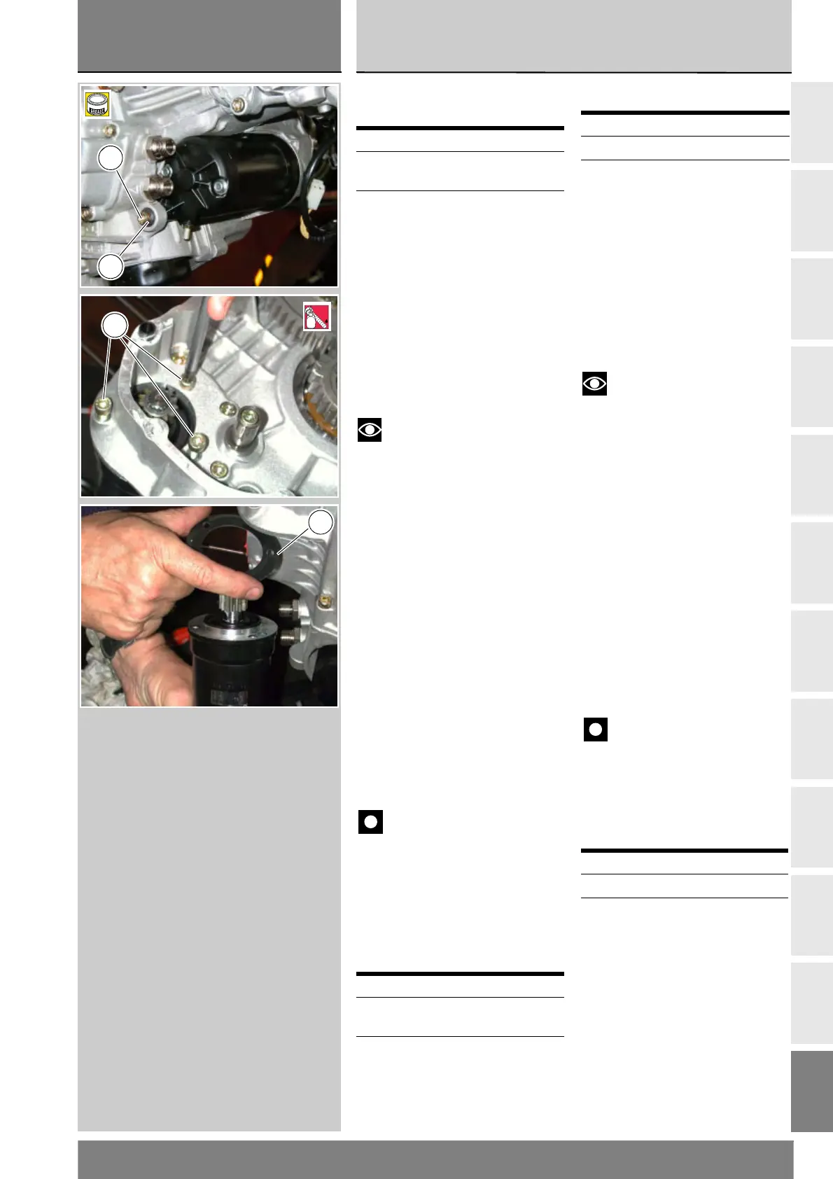
Scollegare il cavo motorino
avviamento / teleruttore (Sez. P 1).
Svitare la vite di fissaggio (1) e se
necessario rimuovere l’inserto (2).
Svitare le viti di fissaggio (3).
Note
Le viti di fissaggio del
motorino d’avviamento sono in
origine montate con frenafiletti.
Estrarre dall’esterno il motorino
d’avviamento e la relativa
guarnizione (4).
Rimontaggio motorino
avviamento
Verificare visivamente lo stato di
conservazione della guarnizione (4)
ed eventualmente sostituirla.
Posizionare la guarnizione (4) e il
motorino d’avviamento sul carter e
avvitare le viti di fissaggio (3) alla
coppia prescritta (Sez C 3).
Inserire l’inserto (2) se rimosso nel
semicarter ed avvitare la vite di
fissaggio (1) e serrarla alla coppia
prescritta.
Collegare il cavo motorino avviamento
/ teleruttore (vedi tavola E).
Importante
Riempire con grasso protettivo
il cappuccio di protezione prima
dell’inserimento sul motorino.
Se è stato sostituito tutto il gruppo
ingranaggi avviamento, rimontare
l’ingranaggio rinvio motorino
avviamento e gli ingranaggi rinvio
distribuzione (Sez N 9).
Operazioni Rif. Sez.
Rimuovere le carene
laterali
E 2
Rimuovere il coperchio
alternatore
N 8
Operazioni Rif. Sez.
Rimontare il coperchio
alternatore
N 8
Rimontare le carene
laterali
E 2
Removing the starter motor
If the whole starting gear unit
needs replacement, remove the
timing drive gears and starter
motor drive gear (Sect. N 9).
Disconnect the starter motor / starter
contactor cable (Sect. P 1).
Remove the fixing screw (1) and,
if necessary, the insert (2).
Undo the retaining screws (3).
Notes
The starter motor retaining
screws are originally assembled
using threadlocker.
Slide out the starter motor and
gasket (4).
Refitting the starter motor
Visually inspect the gasket (4) for
wear and renew if necessary.
Place the gasket (4) and the
starter motor on the crankcase
and tighten the screws (3) to the
specified torque (Sect. C 3).
Position the insert (2) (if removed)
in the crankcase, fit the retaining
screw (1) and tighten it to the
specified torque.
Reconnect the starter motor / starter
contactor cable (see plate E).
Important
Fill the cap with protective
grease before fitting it on the
starter motor
If the starting gears assembly has
been replaced, refit the starter motor
gear and timing gears (Sect. N 9).
Operation See Sect.
Remove the side fairings E 2
Remove the generator
cover
N 8
Operation See Sect.
Refit the generator cover N 8
Refit the side fairings E 2
1
2
B
3
1
LOCK
4