A
B
C
D
E
F
G
H
L
M
N
P
Impianto elettrico
Electric system
sezione / section
P 5
48 749/749 DARK/749S Aggiornamento/Update - M.Y. 2006 - edizione/edition 00
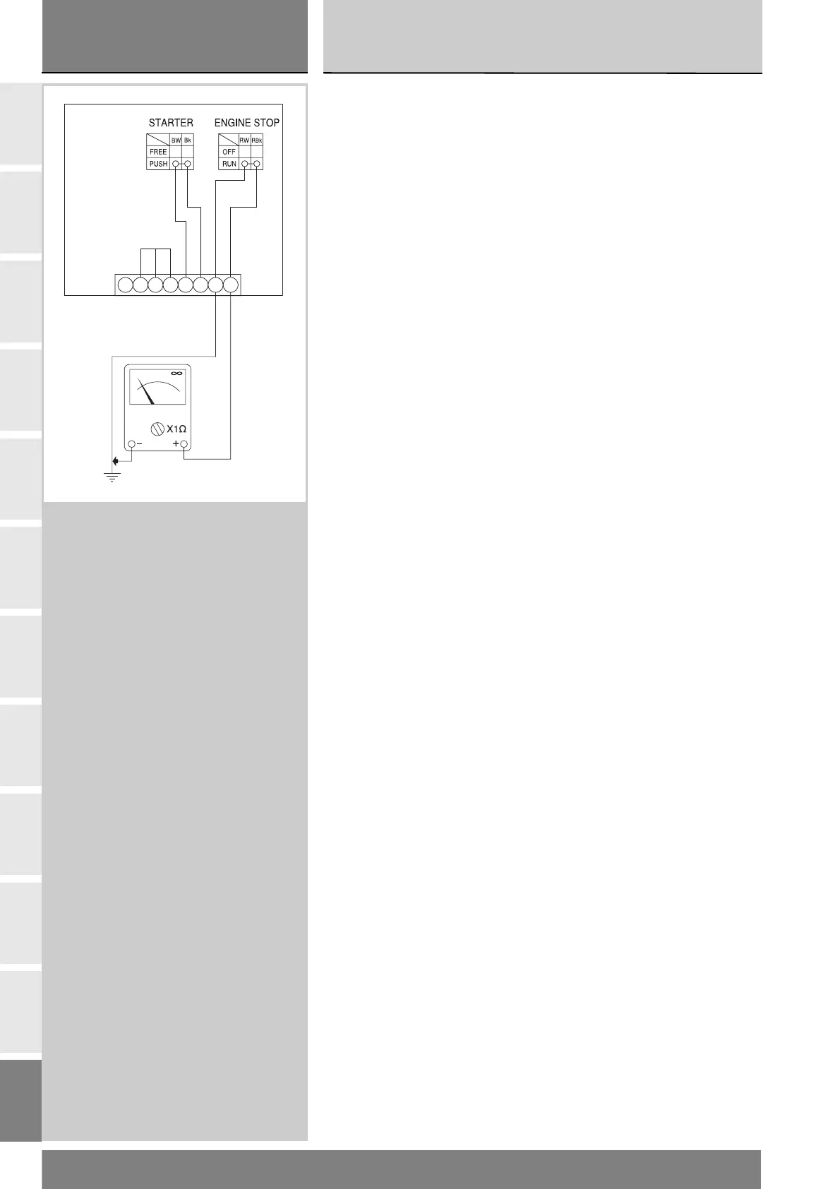
Pulsante starter
Utilizzando lo stesso procedimento
dell'engine stop, verificare la continuità
elettrica tra i cavi (Blu/Bianco e Nero),
premendo il pulsante STARTER
(vedi Sez. P 9).
Se le condizioni di continuità elettrica
non sono verificate il pulsante
STARTER non funziona e va
sostituito. I colori citati si riferiscono
ai fili elettrici che escono dal
commutatore e non ai colori dei fili
dell'impianto elettrico principale.
Deviatore di luce posizione/
anabbagliante
Utilizzando sempre il multimetro
(Sez. P 9) verificare la continuità
elettrica tra i cavi:
(Rosso/Giallo) per la luce
anabbagliante
Il deviatore luci deve funzionare
come segue:
Collegando il multimetro sui cavi
(Rosso/Giallo) mettendo il
deviatore nella posizione luce
anabbagliante, deve esserci
continuità elettrica tra i due cavi.
Se queste condizioni non sono
verificate occorre cambiare il
deviatore delle luci.
Rimontare il commutatore destro
serrando le viti (1) alla coppia
prescritta (Sez. C 3).
STARTER button
Proceed as described for the engine
stop button and check for continuity
between the (Blue/White and Black)
wires when the STARTER button is
pressed (see Sect. P 9).
If there is no continuity, the STARTER
button is defective and must be
replaced. The colours mentioned refer
to the colour of wires coming from the
button and not to the colour of wires
of the main electric system.
Parking light / low beam
headlamp switch
Again with rthe multimeter (Sect. P9),
check electrical continuity between
the wires:
(Red/Yellow) for the low beam
headlight
The light switch should operate as
follows:
With the multimeter connected to the
(Red/Yellow) wires on putting
switch in the low beamposition,
there should be electrical continuity
between the two wires.
If these conditions are not met, the
lights switch must be replaced.
Refit the RH selector switch and
tighten screws (1) to the specified
torque value (Sect. C 3).