9-6
Configuring the E1 + G.703 and T1 + DSX-1 Modules
Configuring the E1 + G.703 Module
Note If you have not yet entered a bind command to join the physical interface to
the logical interface, the channel assignment will not be displayed correctly.
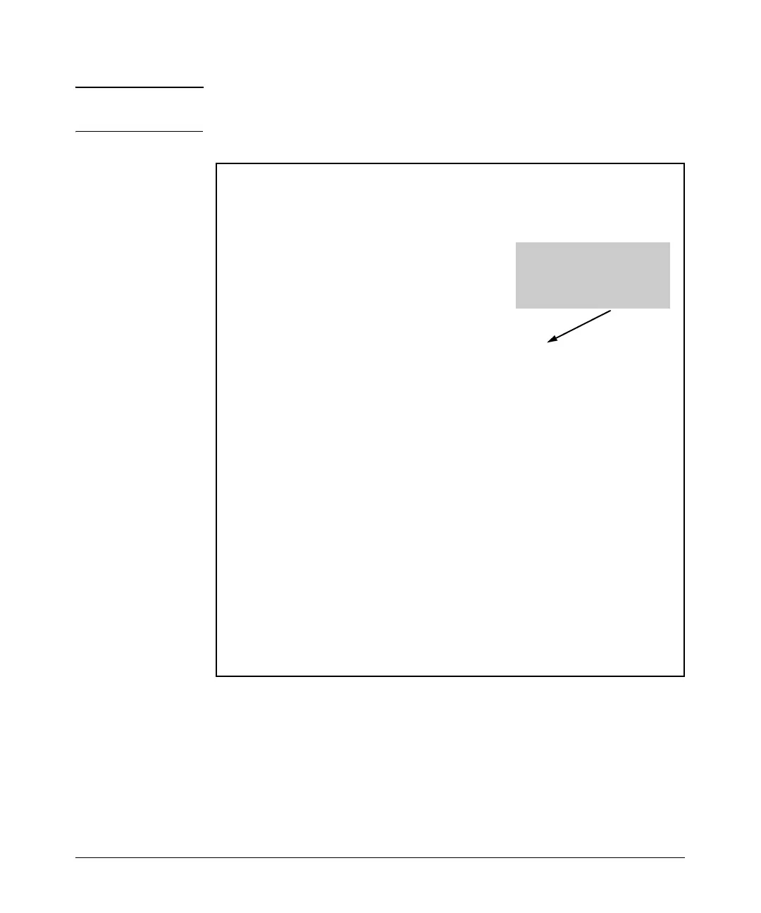
Figure 9-1. Viewing the Channel Assignments for the E1 and G.703 Interfaces
After you ensure that the channel assignments are correct, you will need to
configure the settings for the G.703 interface.
e1 1/1 is UP
Receiver has no alarms
E1 coding is HDB3, framing is E1
Clock source is line
No network loopbacks
Last clearing of counters never
loss of frame : 0
loss of signal : 0
AIS alarm : 0
Remote alarm : 0
Timeslot Status: 01234567890123456789012345678901
FNNNNNNNNNNNNNNNDDDDDDDDDDDDDDDD
Status Legend: '-' = Timeslot is unallocated
'N' = Timeslot is dedicated (nailed)
'D' = Timeslot is allocated to G703 drop port
'F' = Timeslot is dedicated for framing
Line Status: -- No Alarms --
5 minute input rate 120 bits/sec, 0 packets/sec
5 minute output rate 120 bits/sec, 0 packets/sec
Current Performance Statistics:
0 Errored Seconds, 0 Bursty Errored Seconds
0 Severely Errored Seconds, 0 Severely Errored Frame Seconds
0 Unavailable Seconds, 0 Path Code Violations
0 Line Code Violations, 0 Controlled Slip Seconds
0 Line Errored Seconds, 0 Degraded Minutes
TDM group 1, line protocol is UP
Encapsulation PPP (ppp 1)
74 packets input, 4622 bytes, 0 no buffer
0 runts, 0 giants, 0 throttles
66 input errors, 24 CRC, 42 frame
0 abort, 0 discards, 0 overruns
127 packets output, 5554 bytes, 0 underruns
Channels 1-15 are “nailed” to
the E1 interface.
Channels 16-31 are allocated
to the G.703 interface.

 Loading...