9-14
Configuring the E1 + G.703 and T1 + DSX-1 Modules
Configuring the T1 + DSX-1 Module
Configuring the T1 + DSX-1 Module
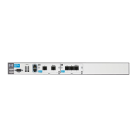
The T1 + DSX-1 module has:
■ a T1 port
■ a DSX-1 port
The T1 port handles the data communications. The DSX-1 port receives all the
channels from the T1-carrier line that are not mapped for data and drops these
channels into a PBX. When you configure a T1 + DSX-1 module, you must
configure it to synchronize the data transfer between the public carrier, the
two ports (or interfaces), and the PBX. You must also configure which
channels are dropped into the PBX.
Making the Physical Connection
The T1 port on the T1 + DSX-1 module includes a built-in CSU/DSU. You use
UTP cabling with RJ-48C connectors to connect the T1 interface to the wall jack
provided by your public carrier. (For more information about the CSU/DSU and
other public carrier equipment used in a T1 connection, see Chapter 4:
Configuring E1 and T1 Interfaces.) You connect the DSX-1 interface to the
PBX, using a crossover cable with an RJ-48C connector.
Configuring the T1 Interface for Data Communications
The first step in configuring the DSX-1 drop-and-insert module is to configure
the T1 interface that will handle data. Two settings for the T1 interface directly
affect the DSX-1 interface:
■ channel assignment
■ clock source
Assigning Channels
When you configure the T1 interface, you assign it a certain number of
channels that will be “nailed” to that interface. By default, any channels that
you do not assign to the T1 interface are passed to the DSX-1 interface.
A T1-carrier line includes a total of 24 channels. When you divide these
channels between the T1 interface and the DSX-1 interface, you must create
two groups of contiguous channels.
 Loading...