6-23
Configuring the Data Link Layer Protocol for E1, T1, and Serial Interfaces
Configuring the Logical Interface
The 10-bit field enables 1024 possible DLCI numbers, but some are reserved
for special purposes:
■ 0 signals Annex A and D
■ 1-15 and 1008-1022 are reserved
■ 1023 signals the Link Management Interface (LMI)
The remaining 976 DLCI numbers between 16 and 1007 are available to users.
Your Frame Relay service provider will assign you a DLCI.
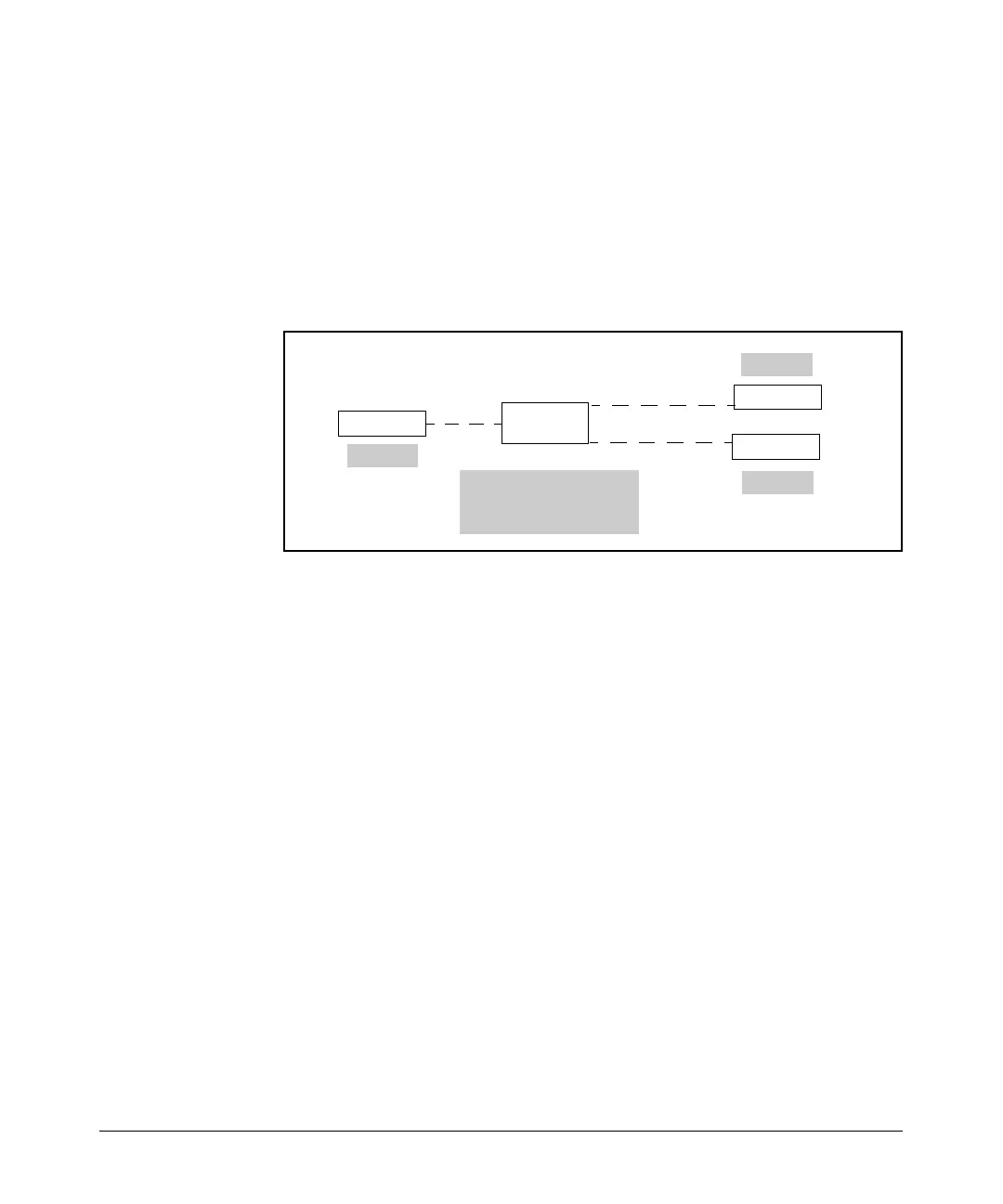
Figure 6-8. The DLCI Identifies the PVC Endpoint.
Create the Frame Relay Interface
To begin configuring Frame Relay as the Data Link Layer protocol for an E1,
T1, or serial interface, you must create a logical interface. From the global
configuration mode context, enter:
Syntax: interface <interface> <number>
Replace <interface> with frame-relay; you can also use the shortcut fr.
Replace <number> with any number between 1 and 1024. Each Frame Relay
interface that you create on the router must have a unique number.
For example, if you are configuring the first Frame Relay interface on the
router, you might enter:
ProCurve(config)# interface frame-relay 1
The router prompt indicates that you have entered the proper interface
configuration mode context:
ProCurve(config-fr 1)#
Each Frame Relay switch
keeps a table of PVC
endpoints and their DLCI.
Router (DTE)
Frame Relay
Switch (DCE)
Router (DTE)
Router (DTE)
UNI
UNI
UNI
DLCI 17
DLCI 18
DLCI 16
 Loading...