4.71.3 Description of the elements
Field Description
PWM 0...n
The description of the PWM output is dis-
played.
The left grey field indicates the current value of
the PWM output. The value "- - -" represents a
sensor error.
The input field in the middle configures the val-
ue the PWM output is forced to (from 0-100%).
If a force is active, the value is represented in
red color.
The right input field activates the force of the
PWM output.
4.72 IO Replace
4.72.1 Purpose
If an IO on a CPU- or IO-Module is defective, it is possible to allocate the de-
fective IO to an other free IO. There is no modification in the software neces-
sary.
Afterwards the IO only has to be rewired.
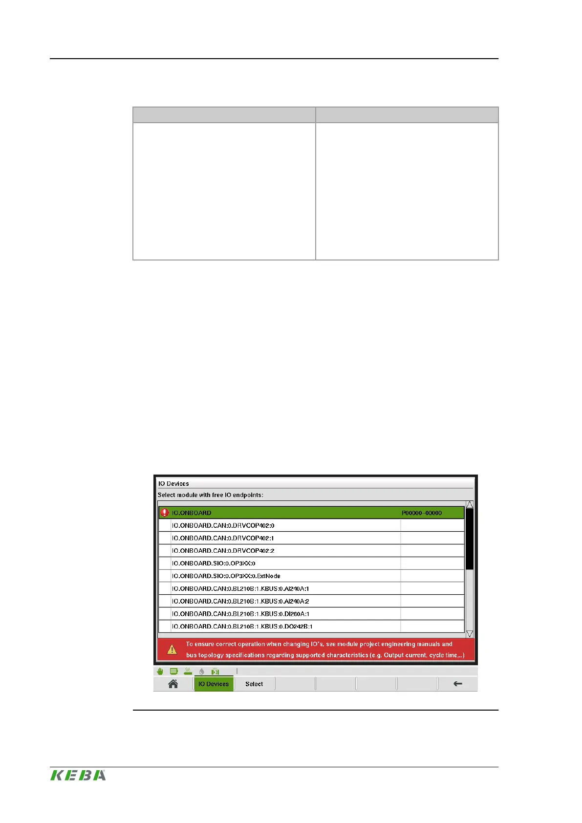
4.72.2 Description of the mask
The mask shows all available Module. To perform an IO- allocation, it is nec-
essary to select the desired IO-module and press button 'Select'.
Fig.4-76: Mask ''IO Replace
Description of the operating masks
KePlast.HMI.KVB
© KEBA 2016
User's manual V3.05158

 Loading...

