4.27.2 Description of the mask
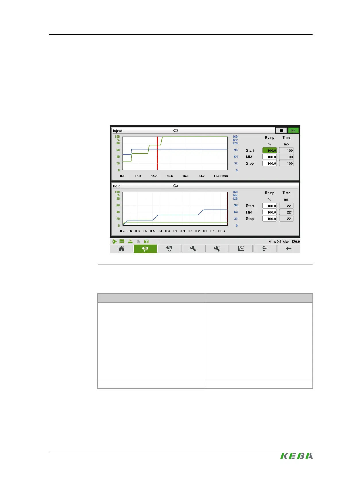
The upper section of the mask displays the inject profile and the lower section
of the mask the hold profile. Arrows on top of the graphics display the direction
of the profile. A red line in the graphics displays the actual position of the
movement.
Further ramp settings for the respective movement can be set. Depending on
the configured ramp setting the corresponding ramp duration for the movement
is calculated.
Fig.4-30: Mask "Inject profile graphic"
4.27.3 Description of the elements
Field Description
Ramp
The ramps [%] for movement start, movement
stop as well as for the inner profile of the move-
ment can be specified. The %- value refers to
the maximum ramp profile output settings that
are configured in setup advanced mask.
● Start: Defines start ramp value for move-
ment.
● Stop: Defines stop ramp value for move-
ment.
● Mid: Defines ramp for all inner profile
ramps for movement.
Time Calculated duration for each ramp.
KePlast.HMI.KVB Description of the operating masks
© KEBA 2016
User's manual V3.05 89

 Loading...

