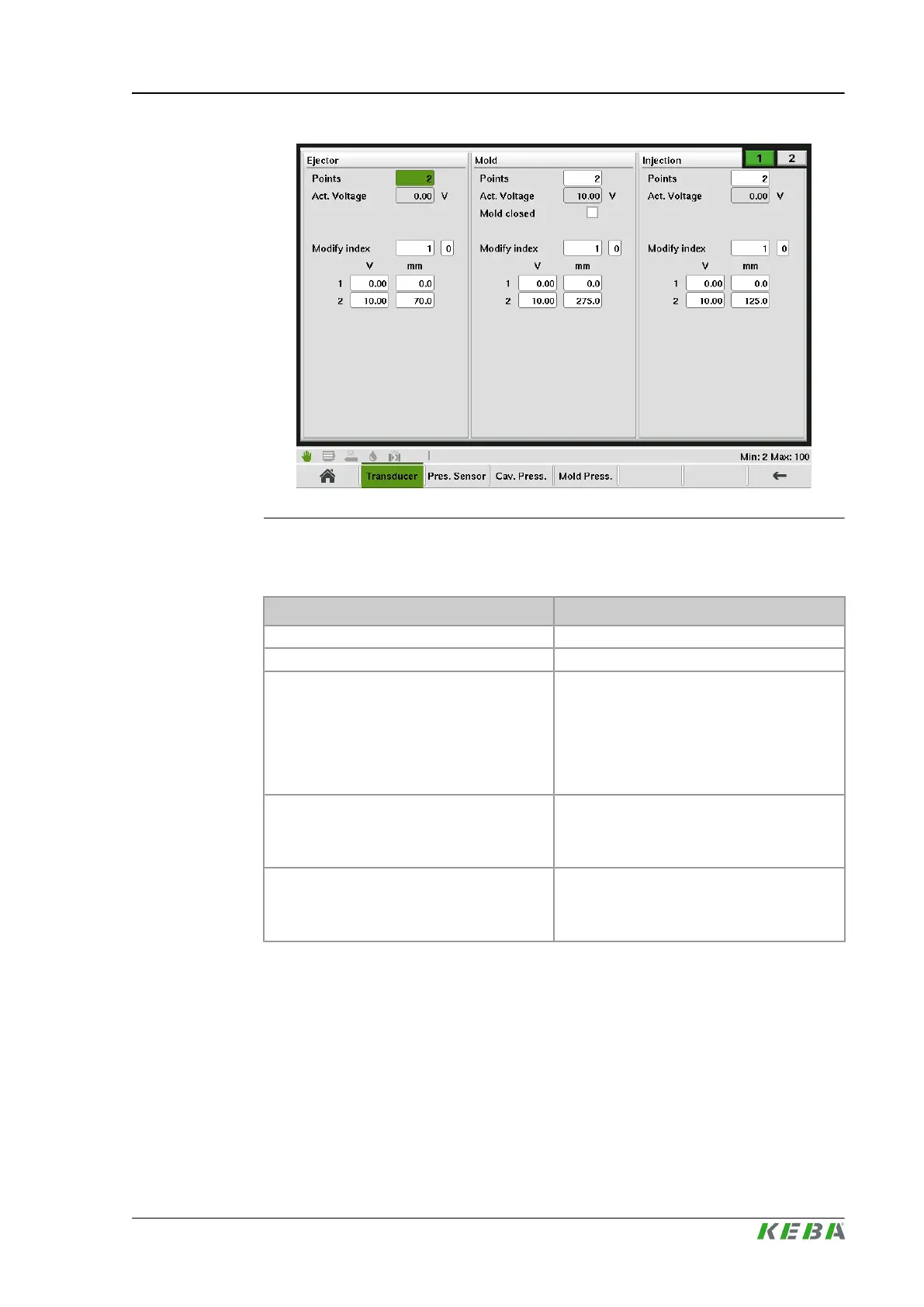
Fig.4-111: Mask "Calibration Trancducer - Tab1"
4.105.3 Description of the elements
Name Description
Points Number of points in the linearization table.
Actual Voltage Displays the actual voltage of the transducer.
Start Index
Since only a maximum of 9 linearization points
can be displayed on the mask, this field serves
for navigation purposes. The input value al-
ways corresponds to the index of the element
displayed first. Example: Value 1: linearization
points 1 to 9 are displayed. Value 17: lineari-
zation points 17 to 25 are displayed, etc.
Modify index
Linearization points can be deleted or added.
The configured index defines which lineariza-
tion point gets deleted resp. after which linea-
rization point a new point gets added.
V / mm
Calibration of a transducer for Mold, Inject and
Ejector. Calibration is done by entering the po-
sition [mm] and the voltage [V] for each linea-
rization point.
4.106
Calibration Trancducer - Tab2
4.106.1 Purpose
This mask is used to manually calibrate the transducers for the nozzle and the
slide table (optional).
KePlast.HMI.KVB
Description of the operating masks
© KEBA 2016
User's manual V3.05 209

 Loading...

