Information
The display depends on the number of heating zones (maximum of 9).
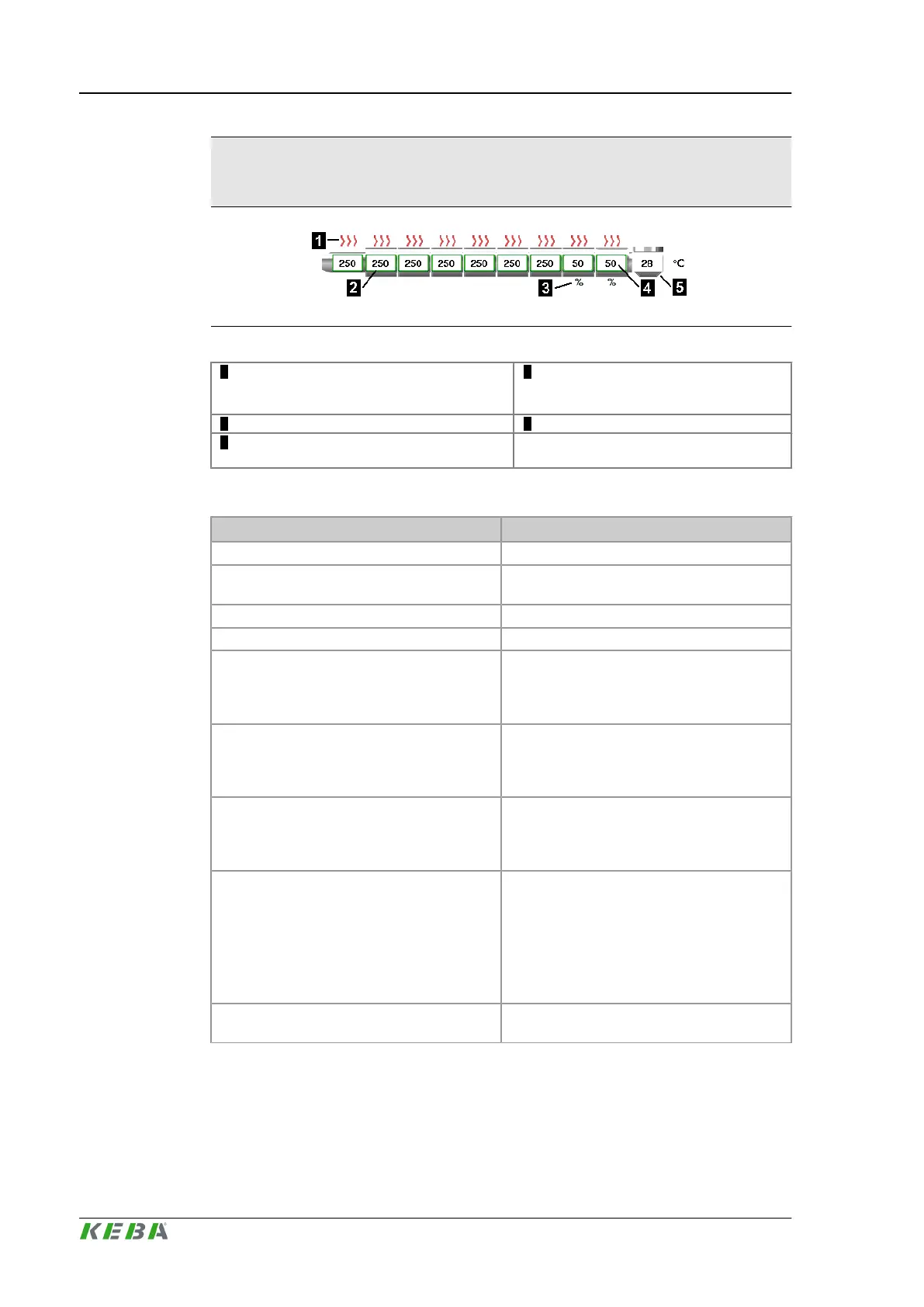
Fig.4-2: Depiction of the heating zones
1 ... Status of the heater (zone is heating / not
heating, error of a heating zone )
2 ... Status of the heater (grey....temper-
ature out of tolerance, green...target
temperature attained)
3 ... %....displays a setter zone 4 ... Actual temperature
5 ... Displays a hopper zone for material en-
trance
Overview data
Designation Description
Pressure Actual system pressure
Velocity
Actual system velocity (displayed in percent-
age of maximum pump flow rate).
Screw rotation Actual screw revolution
Back pressure Actual back pressure
Ejector position
Actual position of ejector in reference to its zero
position (ejector fully retracted. To the left and
right of the analog bar, status marker show if
the ejector has reached on of its end position.
Mold position
Actual distance from movable half of mold to
fixed half of mold. To the left and right of the
analog bar, status marker show if the molf has
reached on of its end position.
Screw position
Actual position of screw in reference to front
end point (end position). To the left and right of
the analog bar, status marker show if the screw
has reached on of its end position.
Nozzle position
Actual position of nozzle, relative to reference
point.. To the left and right of the analog bar,
status marker show if the screw has reached
on of its end position.
This display field is only shown if a transducer
is installed to determine the position of the noz-
zle.
Core position
Actual position of the cores (core in / core out)
displayed by status marker.
Description of the operating masks KePlast.HMI.KVB
© KEBA 2016
User's manual V3.0540

 Loading...

