365-575-102 Circuit Order: NTP-008
Issue 8.0, July 2002 Page 11 of 12
DO ITEMS BELOW IN ORDER LISTED . . . . . . . FOR DETAILS, GO TO
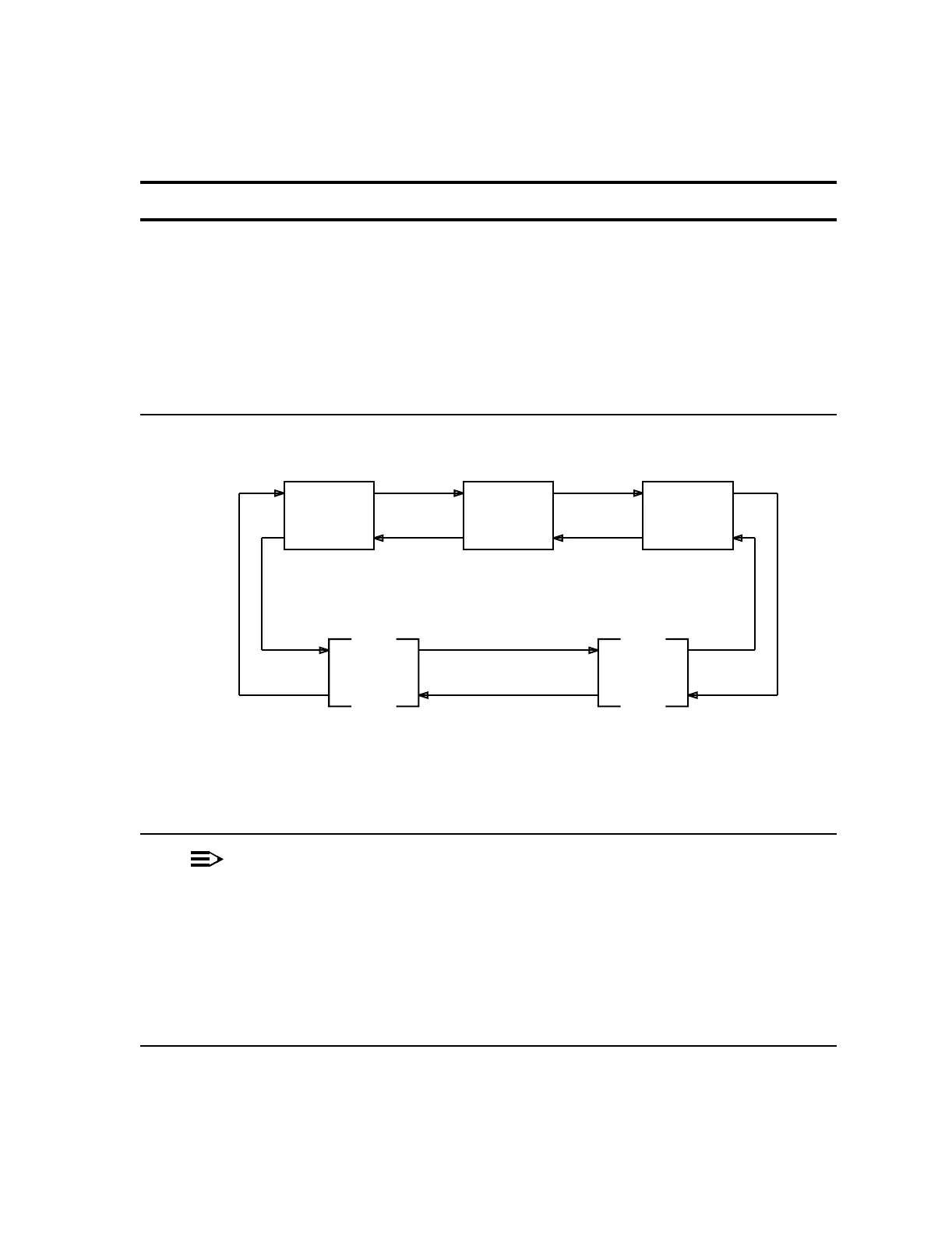
17. Refer to Figure 5. The forced switch at the East node can now be reset.
Instruct the technician at the East node to enter
FAULT-Switch-Line:1E:Reset to reset the
forced switch on line 1W. An alternative method is
to remotely log in to the East node and execute the
command. The line switch may cause traffic hits.
Reference: DLP-524
—
Figure 5 – Ring Network With New Node
18.
NOTE:
The "new node" has NOW been added to the ring network.
Verify that the NE ACTY LED is off at the "new
node" by (1) looking at the LED at the user
panel or (2) using the CIT, log in to the new
nodeandselectFAULT-Retrieve-Network
Alarms command to verify that there are NOT
any active alarms.
—
Line
1W
WEST
NODE
Line
1E
NEW
NODE
EAST
NODE
Other
Node(s)
Other
Node(s)
Line
1W
Line
1W
Line
1E
Line
1E
Line
1E
Line
1E
Line
1W
Line
1W
tpa 832679/01