Motion control C3F_T40
254 192-121102 N04 June 2008
Change-over (CouplingMode = 2)
When using the change-over-function, the curve setpoint value is permanently
displayed during coupling, while the current slave position is permanently hidden.
Overspeeding and pull-out movement are possible.
By specifying the master-related coupling and synchronization position in master
units, the coupling curve is mapped to a range of any length of the curve. This
means that it is no longer fixedly coupled to the curve cycle.
Algorithm of the change-over function
The normalized coupling function begins at the value 0 and end at the value 1 and
rises continually in between. It is a 5th order function.
The coupling curve does not produce a direct slave setpoint value but produces a
factor KE for the weighting of the current curve setpoint value resp. the current
slave position Sa (position at the start of the coupling sequence).
The course of the coupling curve depends on the slave position Sa and the course
of the curve in synchronized operation.
The master speed must be positive, i.e. the master position must be rising.
The weighting is made according to the following function:
coupling curve = SK * KE + S0 * (1 – KE)
with:
S0 = standstill position
SK = current curve setpoint value
KA = control variable between 0 ... 1.0 (between ME and MS)
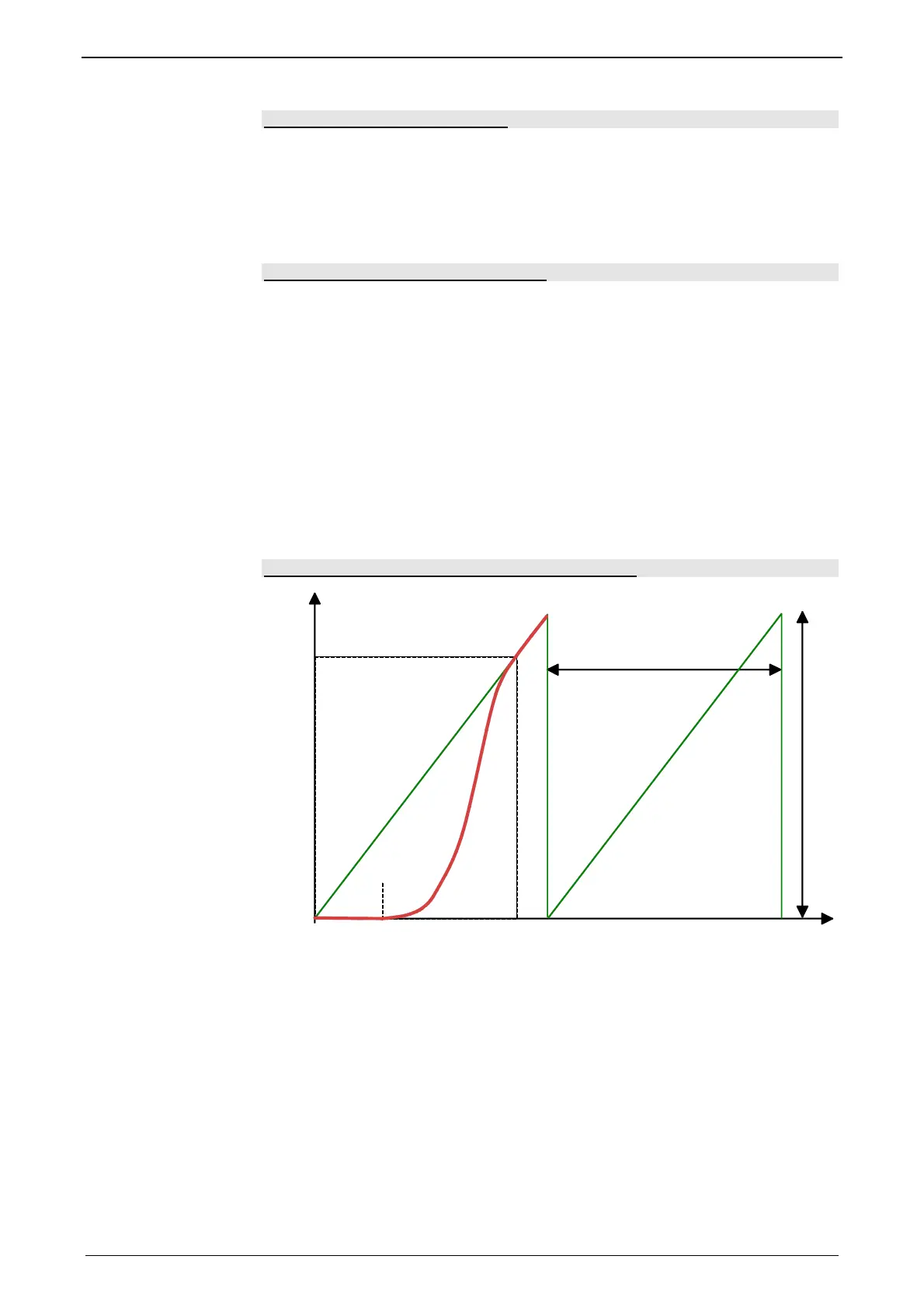
Example: Change-over function over a curve cycle
M
S
Sa
ST
MT
MSME
SS
SS: Slave synchronization position
Sa: current slave position before start of curve
ME: Master coupling position = 30°
MS: Master synchronized position = 340°
MT: Master clock distance = 360°
ST: Slave clock distance
The slope (speed) of the coupling sequence shows a clear overspeeding in
comparison with the synchronized run.

 Loading...


