Hardware Space Components
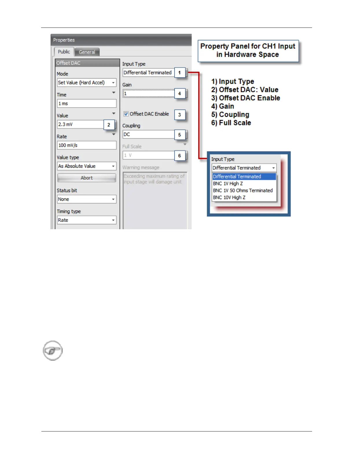
The Input Type (1) drop down box selects the input connector, input impedance, and full scale voltage
range for the Channel 1 Input and Channel 2 Input. The four choices are:
1. Differential Terminated: This input is located on the Preamp Connector. This connector is used when
connecting to one of RHK’s external Preamplifiers, such as the IVP-R9 STM Bias-Preamp Interfaces.
2. BNC 1V High Z: This input uses the BNC connector on the Rear Panel labeled Ch 1 Input. The full
scale input with this setting is ±1V. The input impedance is 1 MΩ.
3. BNC 1V 50 Ω Terminated: This input also uses the BNC connector on the Rear Panel labeled Ch 1
Input. The full scale input with this setting is ±1V. The input impedance is 50 Ω. When this Input Type
is selected, a red LED labeled 50 Ω next to the input BNC will light up.
4. BNC 10V High Z: This input also uses the BNC connector on the Rear Panel labeled Ch 1 Input. The
full scale input with this setting is ±10V. The input impedance is 1 MΩ.
Note
It is important to select the proper Input Type. The 50 Ω should only be used with sources
capable of driving a 50 Ω load. A correct impedance match is especially important when
higher frequency signals are being measured as signal reflections due to a mismatch can
cause significant artifacts.
The Offset DAC (2) data entry box allows a voltage to be added to the input signal to null out the effects
of any offsets in the preamplifier or input circuitry. It also useful when measuring a small AC signal that is
superimposed on a large DC offset. The DC portion of the signal can be subtracted before the AC signal
is amplified and digitized.