Appendix M. Graphically Configured
Oscillators and Lock-in Amplifiers
Modulations and reference frequencies are configured graphically. Typically, the CH1 Drive will be used
as the Master Oscillator and its Reference Frequency will control the behavior of other connected
Hardware Items. The response of the connected items will follow this formula:
Response = ReferenceFrequency * HarmonicFactor + FrequencyOffset
The response will either be an output frequency or a lock-in detection frequency.
Another advantage of this virtual referencing will be that sweeping the frequency of the Master Oscillator
will automatically sweep the frequencies of the connected Hardware Items.
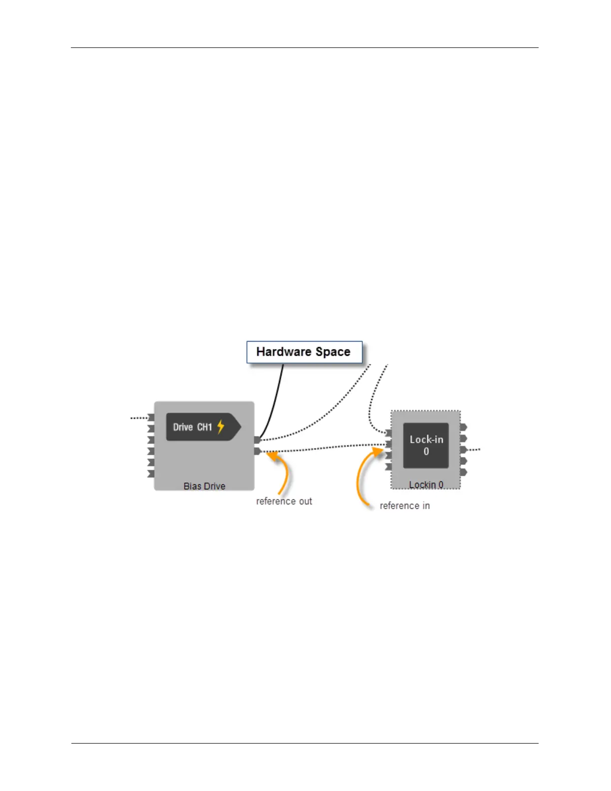
M.1. Typical Example
In the typical example, the Bias Drive Reference Frequency controls the Lock-in Amplifier detection
frequency.
Figure M.1. Typical reference setup in Hardware Space
Many of the controls for Lockin 0 can be hidden when the lock-in amplifier is used in this typical way.
There would be no Frequency Offset required. The Harmonic Factor is set to 1 so that the Lock-in
Amplifier detects at the modulation frequency of the Bias Drive. In this example, the Harmonic Factor and
Actual Frequency are both shown, but they can also be hidden.