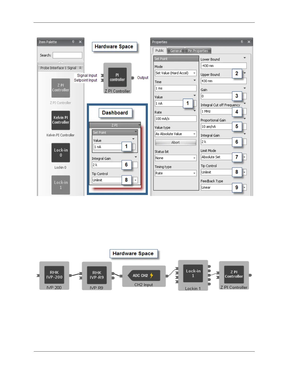
Hardware Space Components
Figure B.16. Feedback Loop Controllers
The Value (1) data entry box sets the Set Point of the Feedback Loop. The unit for the Set Point will be
automatically displayed, based on the unit and scale of the Preamplifier, or External Hardware Device
connected to the Input channel. In the case shown below, the IVP-200 preamplifier has the unit of Amps
and a scale of 100 mV/nA. These parameters are automatically passed from the IVP-200 icon to the
Channel 2 Input Icon to the Lockin 1 Icon and onto the Z PI controller. The only thing the user needs to
do to program the system is to connect the icons together as shown below.
Figure B.17. Feedback Loop Connections
The Upper Bounds and Lower Bounds (2) data entry boxes provide the capability to define the limits of
the motion of the feedback loop. In most Z axis feedback loop implementations, the output value of the
feedback can range anywhere from fully retracted to fully extended. The ability to independently set
Upper and Lower Bounds of the feedback loop provide added experimental flexibility. For example,
instead of freezing the feedback loop to fix the position of the tip above the surface, the Lower Bound
can be set to the present Z position and the Upper Bound can be set for the normal full retract position.
The setting of the Lower Bound will prevent the tip from moving closer to the surface from its present