Significant Changes in R9s 4.0
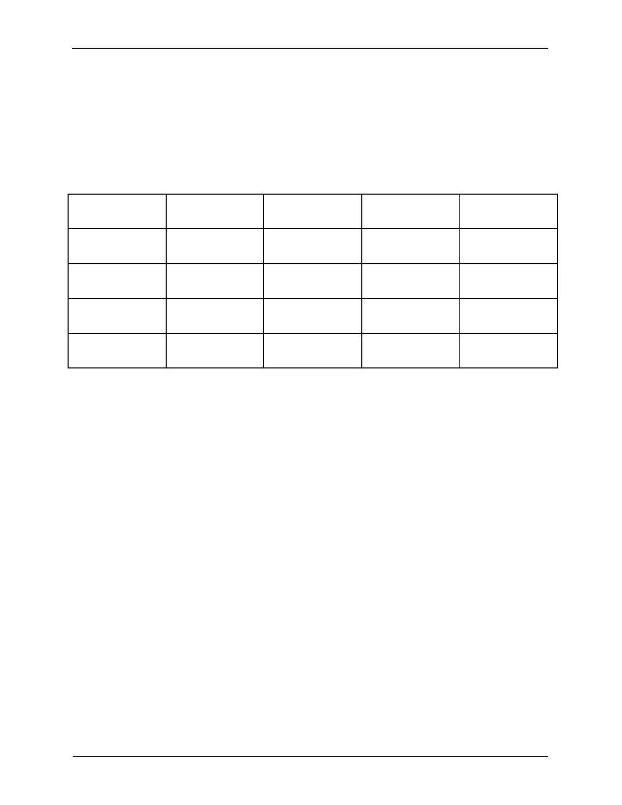
1. The Z-PI Feedback Type Logarithmic and Divide modes have changed greatly in scaling from
previous versions. This should be checked prior to initializing in v4.0 if these modes were being used
previously. The following table provides a guide for how the new values should scale.
2. Addition of the Phase-Locked Loop (PLL): see the PLL section below and PLL Setup Guide for
detailed instruction on using the PLL. The PLL uses lock-in 0 for demodulation and CH2 Drive for a
master oscillator (e.g. probe drive and its own internal reference). So when the PLL is placed on the
hardware space these items are appropriately made unavailable from the hardware drawers.
3. Addition of the Photo-Sensitive Detector (PSD) Alignment Window: this tool was added which allows
the tracking of the laser intensity on the PSD quadrants for an AFM with beam deflection based feedback.
4. Addition of Frequency Sweeps Window: The basic window for looking at the resonance of a cantilever
or tuning fork where a range of drive frequencies is swept with some defined interval and the
corresponding lock-in is referenced to the frequency at each step.
5. Measure Peak: Allows the outer cursors to be dragged with the mouse and they automatically set to
the Start and Stop values on the panel, which are then used in a subsequent sweep.
6. Set Frequency: The middle cursor will automatically be positioned at the frequency where the lock-in
amplitude was maximum. Pressing Set Frequency will drive the resonator at that frequency.
7. Unwrap Phase: Automatically fixes phase wrapping; pressing set frequency after using the Unwrap
Phase procedure is necessary to store the new phase information.
8. Addition of Inteferometric Feedback Module: A panel was added to allow sweeping of the high voltage
DAC associated with controlling the Fabry-Perot cavity length of the etalon (distance between fiber and
cantilever) while monitoring the DC input into the ADC, such that the quadrature point can be chosen and
put under feedback.