Hardware Space Components
both channels. The data recorded is the raw data coming into the Channel 1 Input and Channel 2 Input
without any filtering. This data is constantly flowing into a FIFO buffer. When the Transient Recorder is
triggered, this buffer is sent to the PC for display. The Transient Recorder cannot be used to
continuously stream data at these high rates to the PC. The Transient Recorder can be triggered
manually in the Oscilloscope window, programmatically in Procedure Space, or by detecting a
predefined value or set of conditions in the data stream. A typical use would be to automatically capture
and display the peak amount of current from the STM preamplifier as the STM tip reaches the surface
during the tip approach procedure.
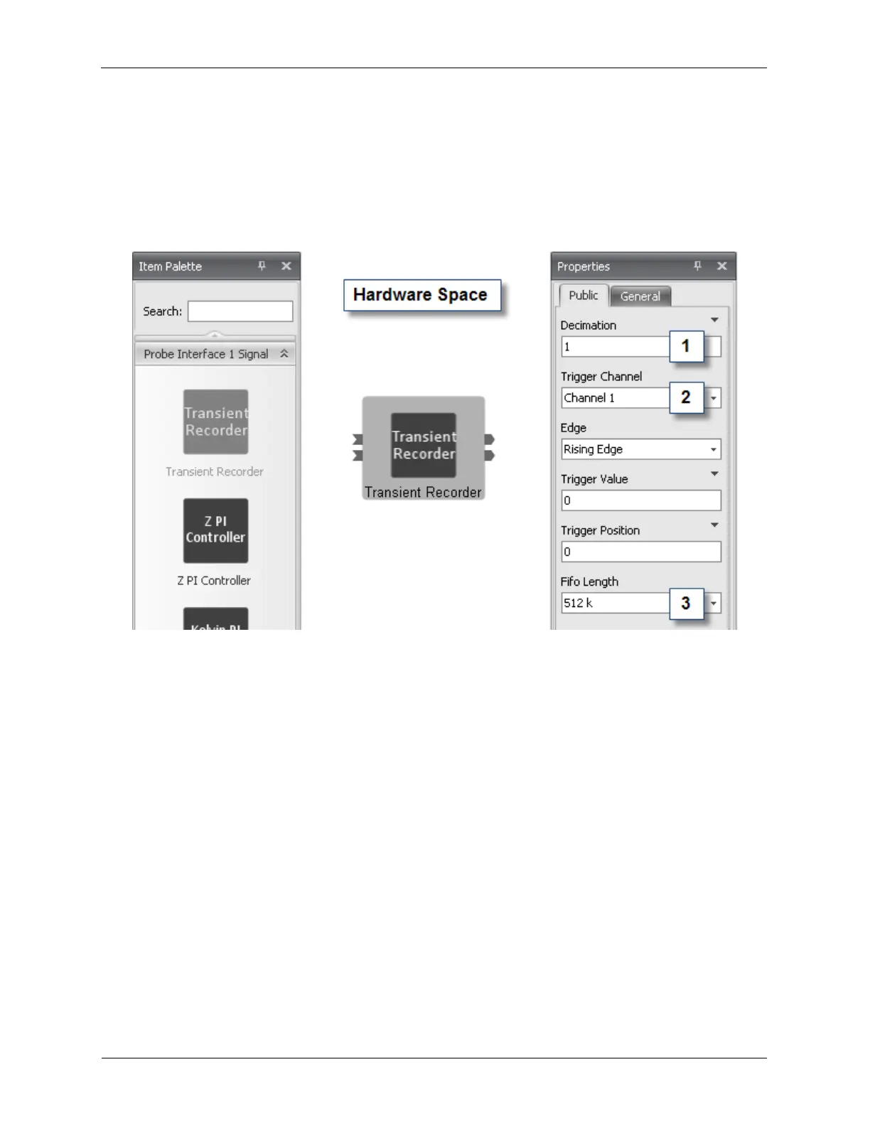
Figure B.25. Transient Recorder
The Decimation (1) selects the number of data samples to be dropped out of the data stream before they
enter the data FIFO. A value of 1 enables the full 100 MS/s to be captured. A value of 2 will reduce the
data sampling rate to 50 MS/s. A value of 3 will further reduce the data sampling rate to 33.3 MS/s.
The Trigger Channel (2) dropdown box selects which channel of data will be used to self-trigger the
capture of data in the FIFO.
The FIFO Length (3) defines the number of samples to be captured. The data capture rate and the FIFO
Length determine the time scale over which the Transient Recorder will capture data. At the maximum
data rate of 100 MS/s and a FIFO Length of 512K, the Transient Recorder can capture data for 5 ms.
Capture Time = NumberOfSamples / SampleRate
B.10. Scan Processor
The Scan Processor icon is found in the Piezo Interface Signal drawer of the Item Palette. The Scan
Processor is a firmware component that controls the motion of the probe during imaging. It generates the
X and Y scan of the probe, as well as the position offsets, drift correction, and slope compensation. The
properties panel in hardware space is typically not used as the controls for the Scan Processor are
located in the Scan Area Window when connected to the Scan Processor as shown below. There is an
input signal on the Scan Processor for the Z signal that is used in the calculation of the slope
compensation and to allow the Z signal to be added to the X and Y scan signal on microscopes that do
not contain a separate Z piezo element.