Connecting the Microscope
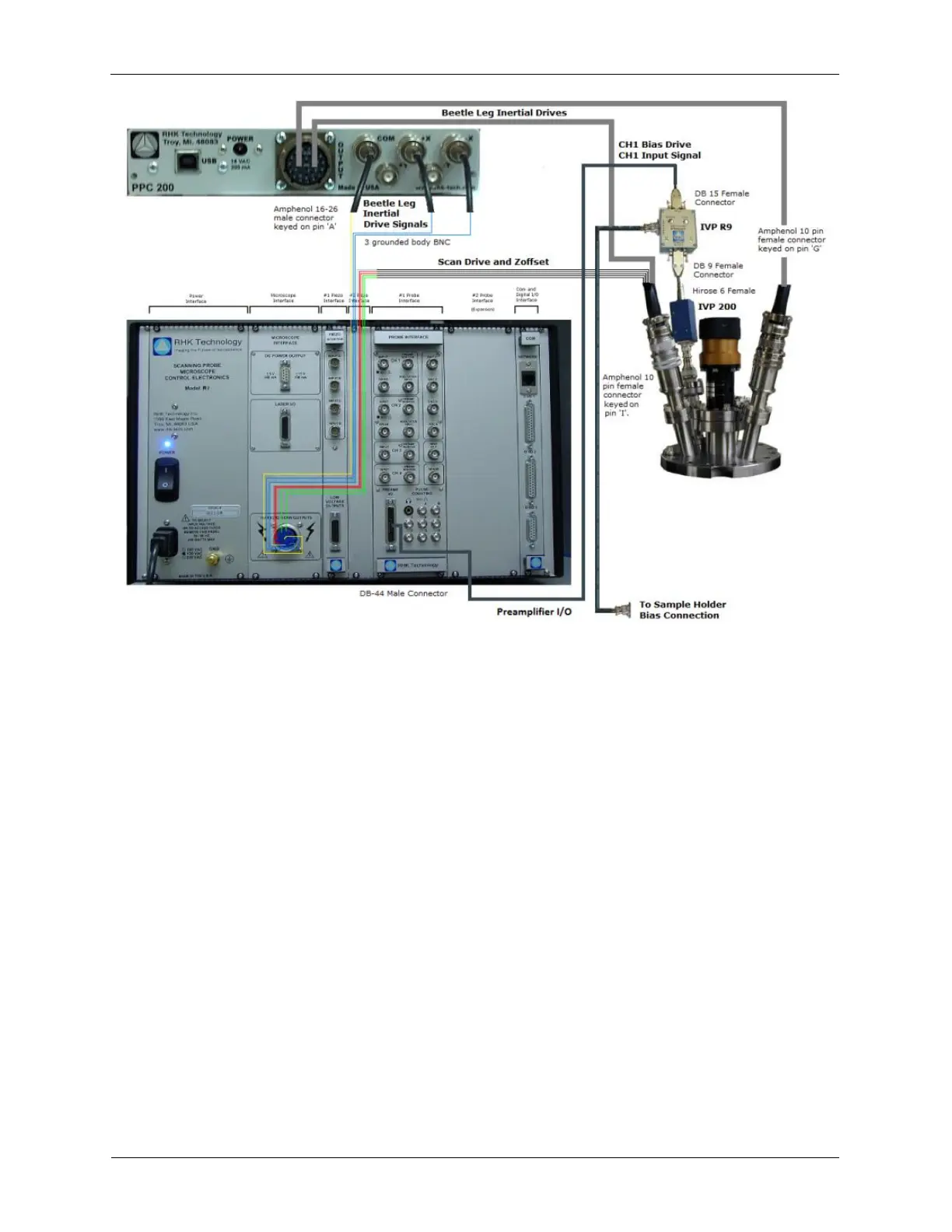
The figure above is a connection diagram of the electronic cable connections between the RHK
UHV300/700 - STM Beetle system, the R9 Controller, and the PPC200. The computer and the
connections between the R9 Controller, the PPC200, and the computer have been left out for clarity, but
are called out in the wiring descriptions below.
1. Turn off the R9 Controller.
2. Connect the Ethernet crossover cable (typically black in color) between the computer and the R9
Controller.
3. Connect the PPC200 to the computer using the supplied USB cable.
4. Connect the High Voltage scan and inertial approach cable.
5. Connect the 26-pin connector to the PPC200.
6. Connect the three approach BNC cables labeled +X Inertial, -X Inertial, and Common, to the +X, -X
and Common on the PPC200.
7. Connect the 10-pin High Voltage connector to the R9 Controller.
Figure C.3. Combined Bias and Preamp Cable