Hardware Space Components
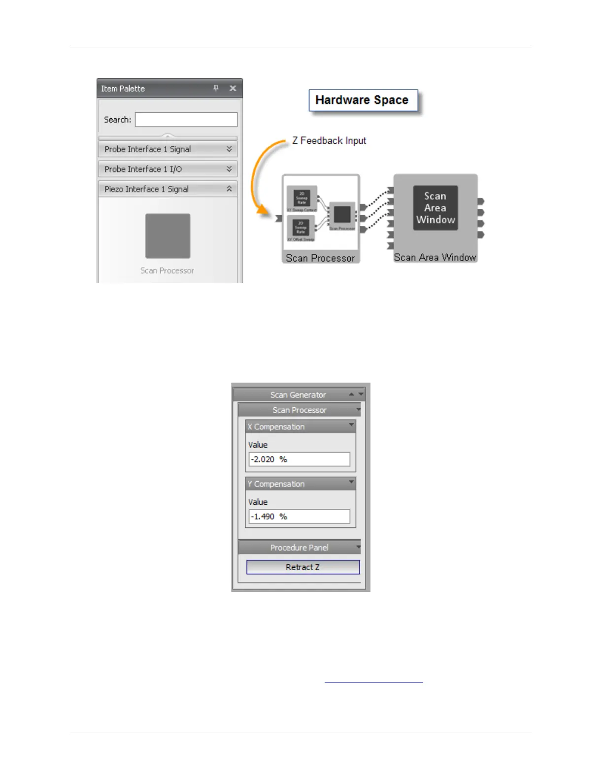
Figure B.26. Scan Processor
B.10.1. Slope Compensation Range
The X and Y slope compensation control accepts percentage values.
Figure B.27. Slope Compensation
B.11. Internal Piezo Modulation
The Internal Piezo Modulation icon is a Numerically Controlled Oscillator (NCO) that is used to
provide modulation on any of the High Voltage Amplifiers. The settings for this oscillator are mostly the
same as those used in the Bias Drive as described in Section 4, “STM Bias”. In addition to the Sine
Output are controls for Attenuation as are present in the Bias Drive. The Internal Piezo Modulation