Hardware Space Components
B.4. CH5 Input
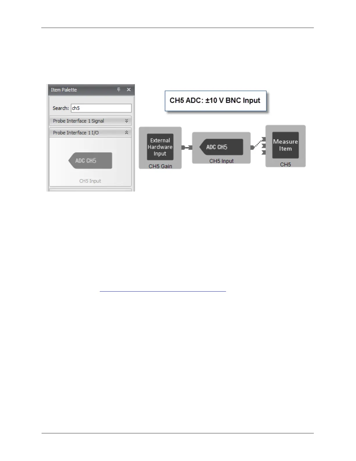
The CH5 Input can accept a ±10 V signal. It has no Offset DAC and no Dashboard controls. The CH5
Input can be connected as shown below.
Figure B.10. CH5 input in Hardware Space
B.5. STM Bias
The STM Bias component is found in the Probe Interface I/O (input/output) drawer of the Item Palette.
The STM Bias is a “virtual” component that does not directly represent a hardware component such as
the ADCs and DACs. The STM Bias component is used to synchronize the polarity of the Bias voltage, in
this case it is connected to Channel 1 Drive with the polarity of the Tunnel Current Set Point and the
Feedback Loop.
To use the Bias Settings component, its Output pin is connected to the Value input pin of the Channel 1
Drive. The Bias Settings (1) component on the Dashboard has control over the output of Channel 1
Drive. The Value (2) data entry box in Channel 1’s R9 control will be disabled. For details on operating
the Bias Settings, see Section 5.3, “Adjusting Bias Voltage Parameters”.
Figure B.11. STM Bias