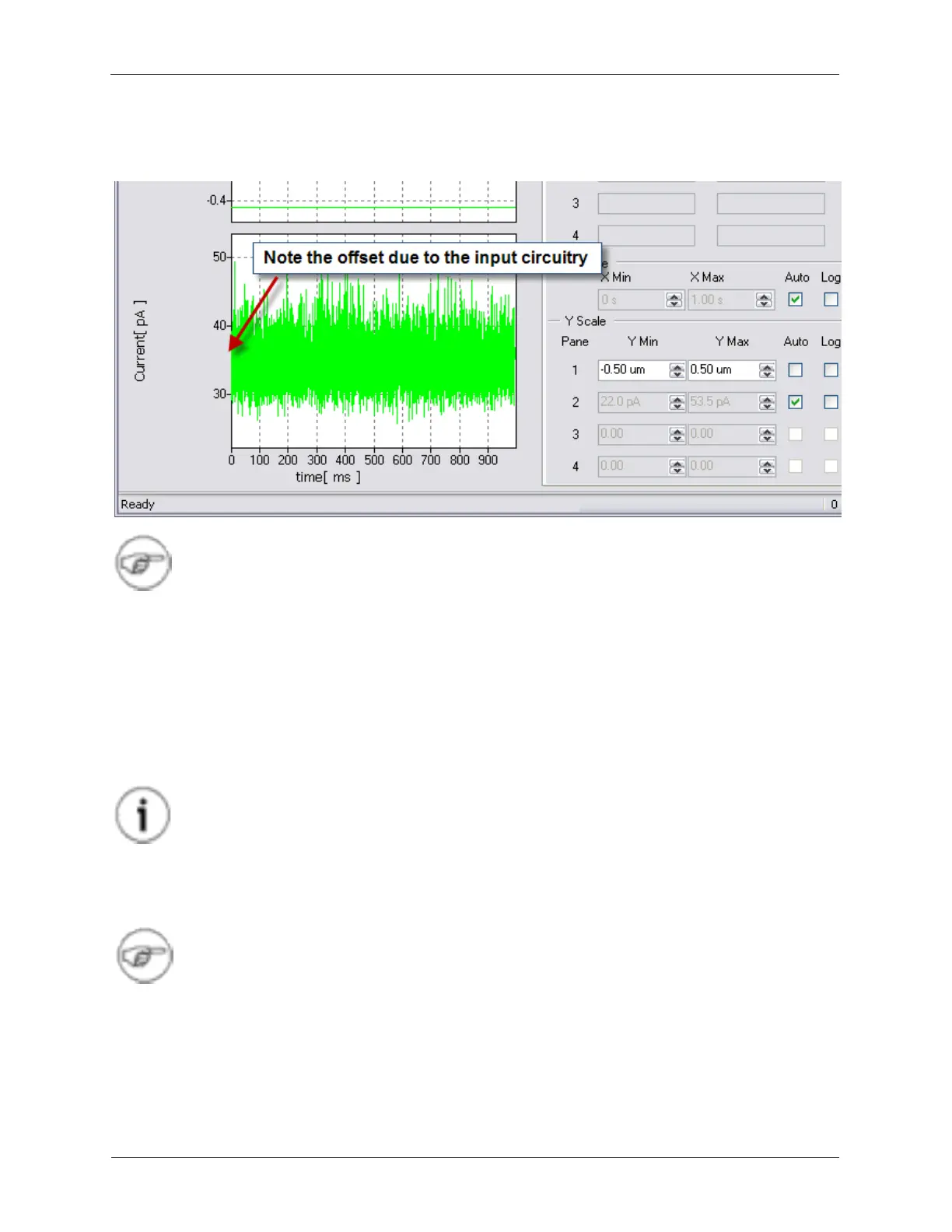
The data trace for the Current can now be seen on the Oscilloscope. A typical example is shown below.
Figure 1.15. Testing the Input Offset
Note
As it can be seen, the noise level is greater than what was measured without a preamplifier
connected. This shows that the noise floor of an STM experiment is generally limited by the
noise of the preamplifier.
The amount of Current displayed on the Oscilloscope should be centered around zero nA. It is typical
that there is some offset due to the input circuitry and the preamplifier itself. The offset of the current can
be nulled to zero through a software controlled input offset circuit.
On the Dashboard, find the control for Channel 2 Input Offset. By adding and subtracting a value, such
as 1 nA, the oscilloscope trace will shift by the same amount. This shows that the input offset circuit is
working correctly.
Tip
To set a value in a data entry box, click the mouse onto the digit that is to be changed. The
up and down arrow keys will increment and decrement this digit. The left and right arrow
keys will move the highlighted digit that is to be changed to a more or less significant digit.
The number of displayed digits, and therefore the amount of precision, can be set by the
user by simply typing in a number with the desired number of digits after the decimal point.
Note
R9 works with SI units and will automatically switch ranges when appropriate.
To further characterize the preamplifier, a power spectrum of it's noise can be acquired.
1. On the ADC Channel 2 Lock-in filter drop down box (on the dashboard), select the No Filter setting.
2. Open the Spectrum Analyzer on the Ribbon.
3. Under the Curves tab, select Current.