Appendix B. Hardware Space
Components
As has been previously explained, R9 Software is separated into three distinct sections: Hardware
Space, Procedure Space, and the Dashboard. Each item that is placed on the Hardware Palette can
be manipulated in all three spaces. The controls for these manipulations are similar in all three spaces,
but there are also important differences.
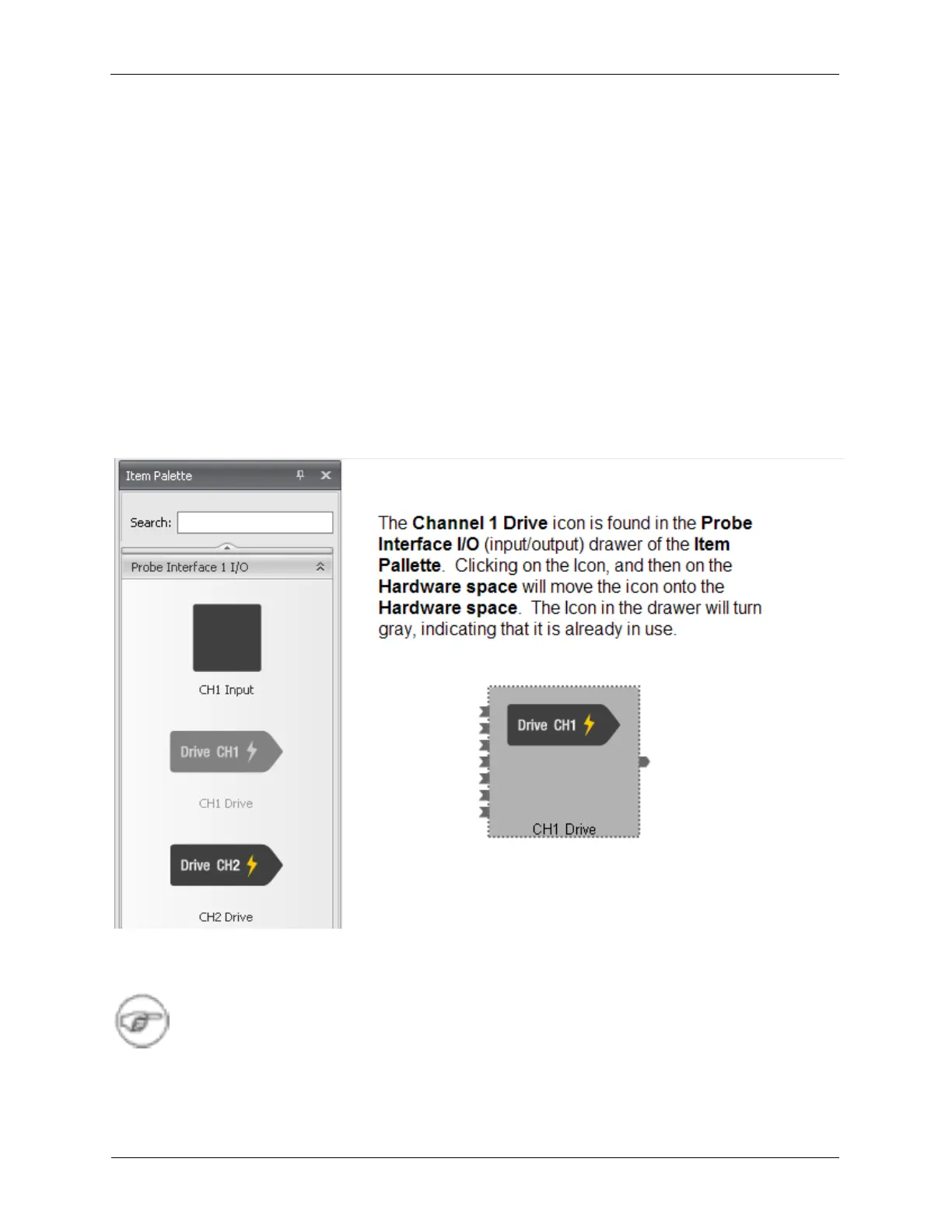
B.1. Channel 1 Drive and Channel 2 Drive
The Channel 1 Drive is used for the below examples, assuming it is connected to the sample in an STM.
The Channel 2 Drive is identical to the Channel 1 Drive.
B.1.1. Hardware Space
Figure B.1. Channel 1 Drive - Hardware Space
The Output of the Channel 1 Drive is connected to both the CH 1 Drive BNC as well as to the differential
preamp connector.
Note
The CH 1 Drive and CH 2 Drive BNC outputs are 50 Ω output impedance. They should be
connected to a device with a 50 Ω input impedance, or terminated with a 50 Ω terminator. If
these BNC outputs are not driving a 50 Ω load, their output will be double the expected
value.