Hardware Space Components
B.15. TTL Inputs and Outputs
There are eight TTL Input lines and eight TTL Output lines available for handshaking and trigger
applications. The TTL lines are broken into blocks of four TTL lines each. The TTL I/O icons are found in
the Communication, Network, and Digital Input/Output (DIO) drawer of the Item Palette. These TTL
lines are part of a 32-bit word that are broken into Nibbles (four bit block) for ease of use.
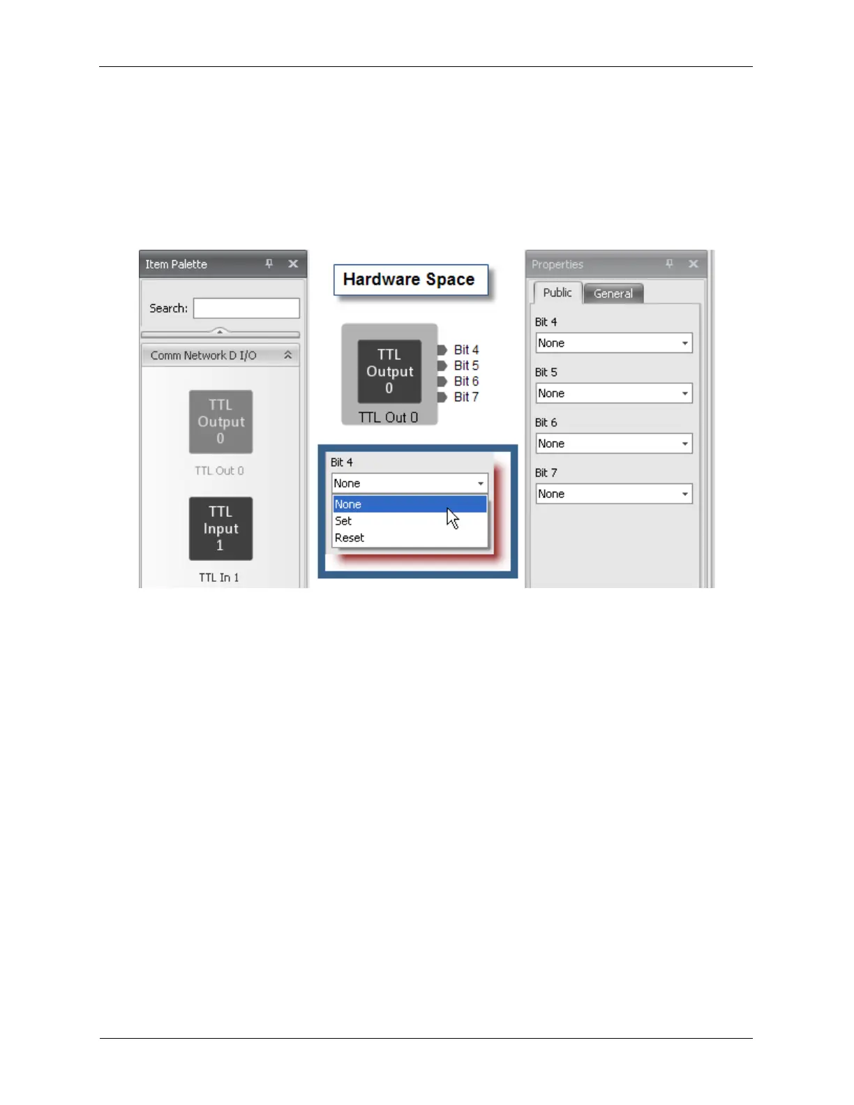
Figure B.34. TTL Output
• TTL Out 0 represents BYTE 0. Bits 4-7 are available for use. Bits 0-3 are reserved for future use.
These four bits are outputs.
• TTL In 1 represents BYTE 1. Bits 4-7 are available for use. Bits 0-3 are reserved for future use. These
four bits are inputs.
• TTL Out 2 represents BYTE 2. Bits 4-7 are available for use. Bits 0-3 are reserved for future use.
These four bits are outputs.
• TTL In 3 represents BYTE 3. Bits 4-7 are available for use. Bits 0-3 are reserved for future use. These
four bits are inputs.
Each TTL Out bit has three settings:
• Set: This sets the bit to a logic level high.
• Reset: This sets the bit to a logic level low.
• None: This does not set the bit high or low, but leaves it at its current setting.
Upon power up, the value of each TTL bit will be set according to the value set on the Properties panel
in Hardware Space. It is best that they be defined either Set or Reset so they are in a defined state.
When setting any bit in a DIO block, the software will update all four bits. If only Bit 4’s value is to be
changed, set the dropdown box for Bits 5-7 to None so their existing value is not changed. Any number of
bits can be changed during a single operation.