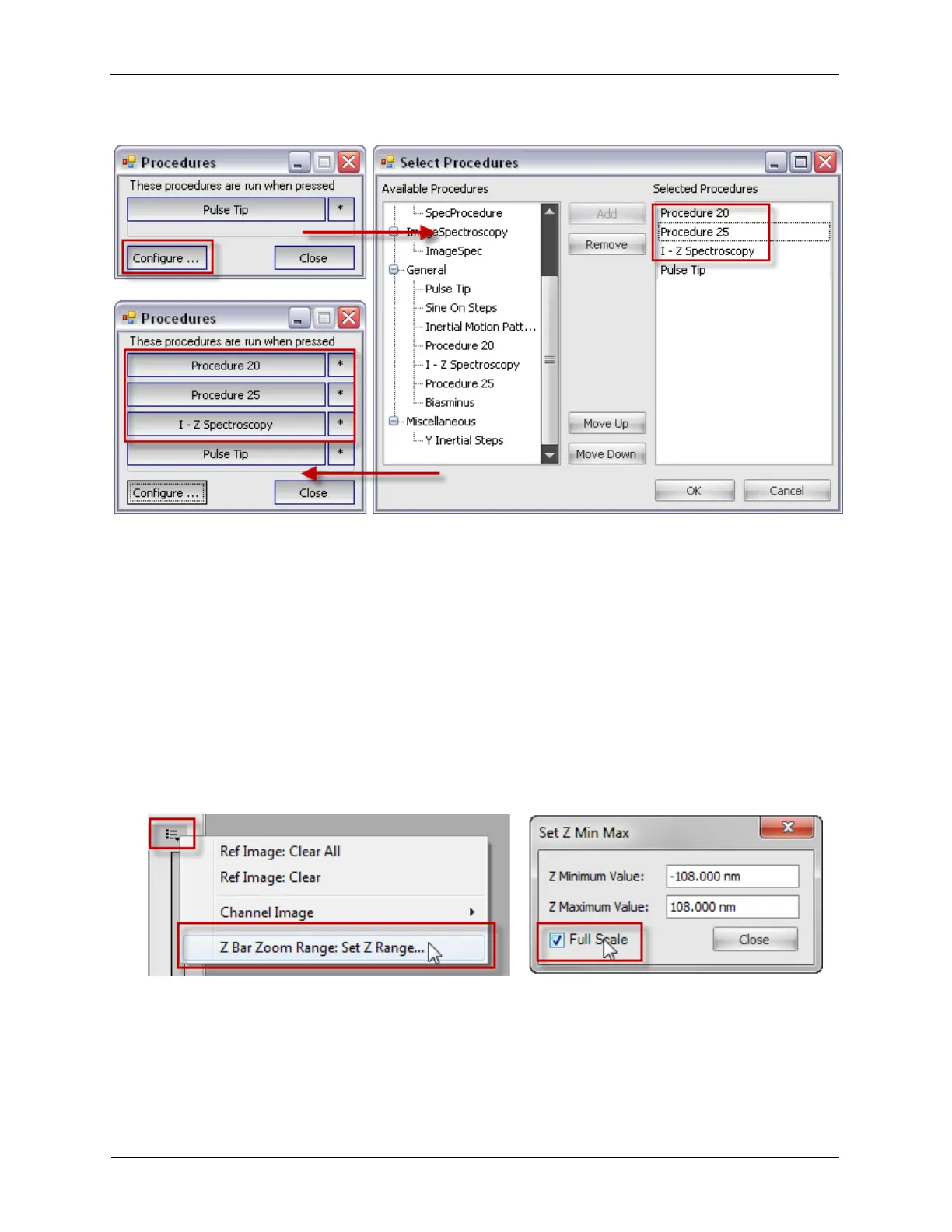
Figure K.4. Configuring Procedure Panels
7. Scan Area Adjustment Buttons: The Arrow buttons can move the Scan Area to a different location in
the Scan Range. The Square button centers the Scan Area in the middle of the Scan Range. The other
buttons are for rotating the Scan Area clockwise, counterclockwise, or zero rotation.
8. Scan Mode: This sets the acquisition mode to either Image, Spectroscopy, or
Image+Spectroscopy.
9. Procedure Pattern: The pattern tells the software which locations to acquire the spectral data, such as
the tip's Present Position, or at Every Pixel while taking an image.
10. Scan Area Window Option Menu: The two important functions of the Option Menu are to select
which Imaging Channel should be displayed in the Scan Area while taking an image (Channel Image) and
to set the Maximum and Minimum values for the Z Feedback Meter. The Z Feedback Range can
automatically be set to use the Full Scale value of the Z output.
Figure K.5. Z Feedback Meter Set Range
11. Z Feedback Meter: The Z Feedback Meter shows the tip's relative Z-position with respect to the
feedback output.