External Control Interface
Appendix N. Phase-Locked Loop (PLL)
A PLL is a commonly employed tool in AFM for locking the phase between the AC drive signal
to the resonator (e.g. a cantilever, tuning fork, etc.) and the signal input. When the phase is
locked, the resonance frequency of the resonator will shift when the tip interacts with the
surface. This can be fed to the Z-PI controller and used for feedback, and then the error signal
would actually be the dF rather than the output from the lock-in amplifier itself. This modality is
commonly referred to as non-contact AFM (NC-AFM).
The R9 PLL has an additional feedback loop that can hold a setpoint of the lock-in signal by
varying the drive amplitude to maintain the setpoint. In this case, both feedback loops would be
active and either dF or the drive amplitude error signal (dissipation) could be fed to the Z-PI
controller.
The general idea of the PLL's function is to demodulate an input based on a reference
frequency while using its two feedback loops to regulate other signals that are affected by the
input. The detailed theory of operation is outside the scope of this document.
PLL uses CH2 Drive (for modulation) and Lock-in 0 (for detection) so these will be unavailable
while the PLL is used in Hardware Space. Likewise, if either CH2 Drive or Lock-in 0 are in use
in Hardware Space the PLL will be unavailable.
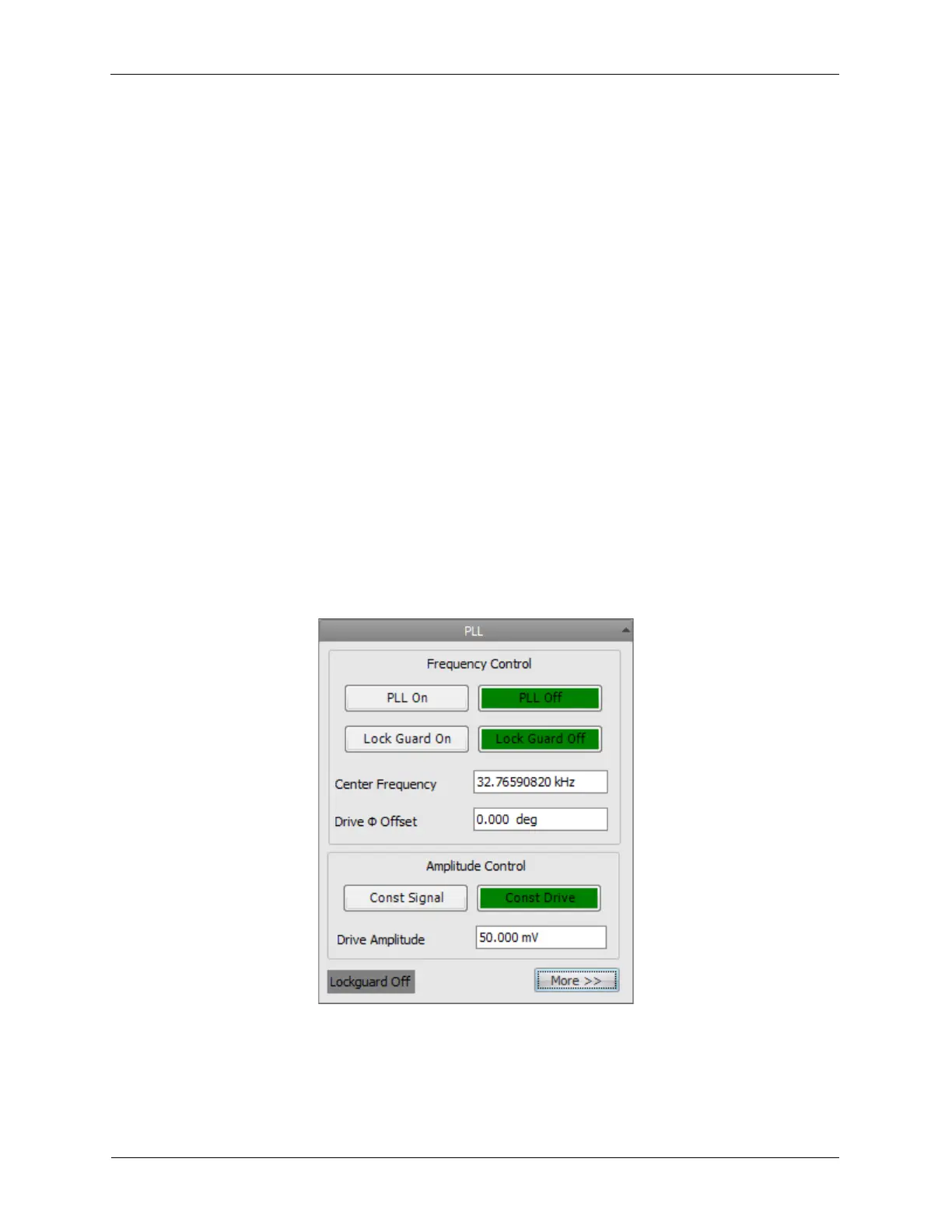
Please refer to the PLL Setup Guide for an introduction to the PLL.
Figure N.1. Phase-Locked Loop
N.1. PSD Alignment Window
The PSD Alignment Window is a tool used to track the laser intensity on the PSD quadrants in a
beam-deflection AFM. The intensities are shown as a red dot that moves relative to the bending