Figure 1.18. Bias Voltage and CH1 Drive Settings
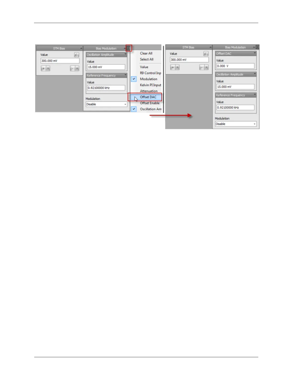
The value of the Bias voltage, 1V, should now be shown on the DVM. If the voltage is not exactly 1V, the
offset can be nulled out with the Offset DAC. If the reading on the DVM shows 1.002 volts, setting the
Channel 1 Drive Offset DAC to -2 mV will bring the reading on the DVM closer to 1.000V. To drive the
DVM exactly to 1.000, the Offset DAC can be set to even higher precision, such as -2.01 mV. As
mentioned previously, the offset adjustments should be made after the unit has reached thermal
equilibrium. Once set, these controls can normally be hidden on the dashboard.
As different voltage values are entered into the Bias Voltage data entry box, the entered voltage will be
output and displayed on the DVM. Only positive values can be entered into the Bias Voltage data entry
box. An attempt to enter a negative number will be rejected. To set a negative bias voltage, click on the "-
" button in the Bias Voltage data entry box. When switching from positive to negative bias voltages a
string of events occur.
1. The feedback loop is frozen.
2. The bias voltage ramps at a preset rate from the positive value displayed in the control to its negative
value.
3. The polarity of the Z PI feedback loop's Setpoint, proportional gain and integral gain are inverted.
4. The feedback loop is re-activated.
This procedure assures that no transients are applied to the tip/sample when the polarity is inverted. Click
on the "C" (for Configure) button in the STM Bias data entry box. A new dialog will be opened that has
two parameters:
1. Limit: This control sets how close to 0V the bias voltage will be allowed to be set in the Bias Voltage
data entry box. This prevents a tip crash if the bias voltage is accidentally set to 0V while using the up
and down arrow buttons to set the bias voltage. It also prevents a tip crash if the bias is set to a value
that is less than the offsets of the ADC input channel or the Bias Drive output. A typical value for the
limit is 10 mV. If a bias value of less than 10 mV is desired, care should be taken that the input and
offset offsets have been nulled to close to zero.
2. Rate: This control sets the rate that the bias voltage will change when the value is changed in the data
entry box. This defined slew rate prevents a transient pulse that could modify the tip or sample. Almost
every parameter that can be set in the R9 has the capability to set a slew rate to prevent sudden jumps
in values. These controls will be described in a later section. A typical value for the Rate is 1V/s.