• Increasing the Setpoint allows the tip to follow the surface at a closer distance in order to resolve more
detail. Decreasing the Setpoint allows the tip to follow the surface at a further distance to avoid
contacting with molecules and contaminations that are adsorbed on the surface.
• Scanning a larger area allows the user to survey the sample to find a clean spot to zoom in. However,
scanning a larger area may require a slower scan speed to avoid collision of the tip and sample.
• Scanning at an angle allows the tip to scan the surface with rotated slow scan orientation. Remember,
when an STM scans a sample, the tip is much more sensitive when it scans across a feature rather
than parallel to a feature. Rotating the scan angle allows the slow scan orientation to be aligned as
close to a right angle to the feature as possible.
• When the STM scans across the surface, the speed of the tip needs to be slow enough to allow the
feedback loop to have sufficient time to react to the topography of the sample. However, having the
scan speed too slow also makes the image more affected by thermal drift.
Tip
The Image Line is a very useful tool to help optimize imaging parameters. When scanning
the surface with a good Setpoint and feedback gain, the Image Line represents the true
topographic height of the sample instead of noise or tip-sample disengage. Therefore, the
forward and reverse Image Lines should have the sample's shape.
Tip
Users can change the Scan speed during image acquisition. The size change will take effect
on the next scan line. The scan area window will still be displaying the image over the original
size but the image windows will reflect the updated scan size.
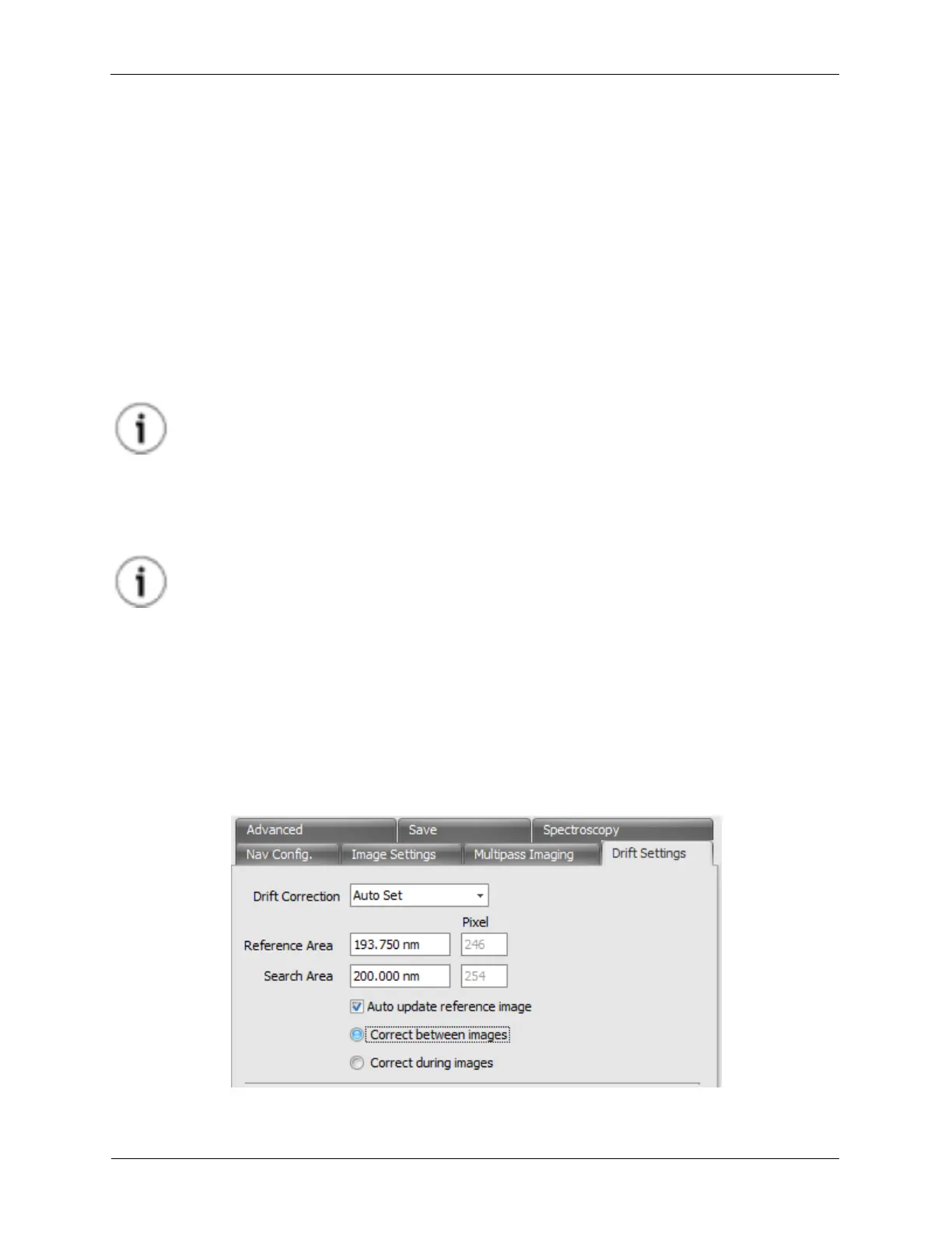
4.5 Drift Correction
You will notice there is a Drift Settings tab on the Scan Area Window. We have three Drift Correction
modes: Off, Automatic and Manual. Then there are two Drift Modes: Correct between images will add
an XY Offset after completing an image scan and Correct during images will add an XY Offset after
completing an image as well as continuously add an offset into the XY Scans.
Figure 4.9. Scan Area Window - Drift Settings