Hardware Space Components
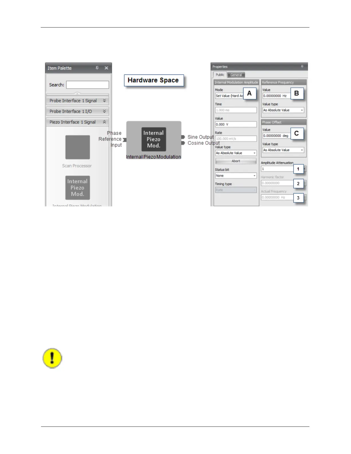
also has a Cosine Output. The Phase Reference Input can be connected to the Phase Reference
Output of another Hardware Item if the modulation frequencies should be synchronized.
Figure B.28. Internal Piezo Modulation
The Internal Modulation Amplitude (A) is an R9 Control that accepts a Value in the range of 0 to 1 V,
where "1 V" represents a modulation over the full range of the HVA. For example, if an Internal
Modulation Amplitude of 0.1 V is summed into a HVA with an output range of ±150 V, the HVA output
will be modulated ±15 V.
The Reference Frequency (B) controls the modulation frequency of the HVA. This control will become a
Frequency Offset if the Phase Reference Input is connected to another Hardware Item.
The Phase Offset (C) can be used to adjust the phase of the Internal Piezo Modulation output.
The Amplitude Attenuation (1) is a specialized control that helps to optimize the Internal Piezo
Modulation when very low signal levels are needed. When a Modulation Amplitude of more than 10
mV is being used, the Amplitude Attenuation can be left at 1.
The Harmonic Factor (2) is enabled when the Phase Reference Input is connected to another
Hardware Item.
The Actual Frequency (3) will display the real output frequency of the Internal Piezo Modulation. The
Actual Frequency is only helpful to see when the Phase Reference Input is connected to another
Hardware Item.
Important
In that case: ActualFrequency = ReferenceFrequency * HarmonicFactor +
FrequencyOffset.
An example output of the Internal Piezo Modulation is shown below.