Appendix I. Details on an IHL File's
Construction
The following Appendix will describe the elements of an IHL file used for an RHK UHV STM microscope.
The individual components are briefly described along with the basic rules to connect them together.
More detailed descriptions of the individual components are provided in the previous sections.
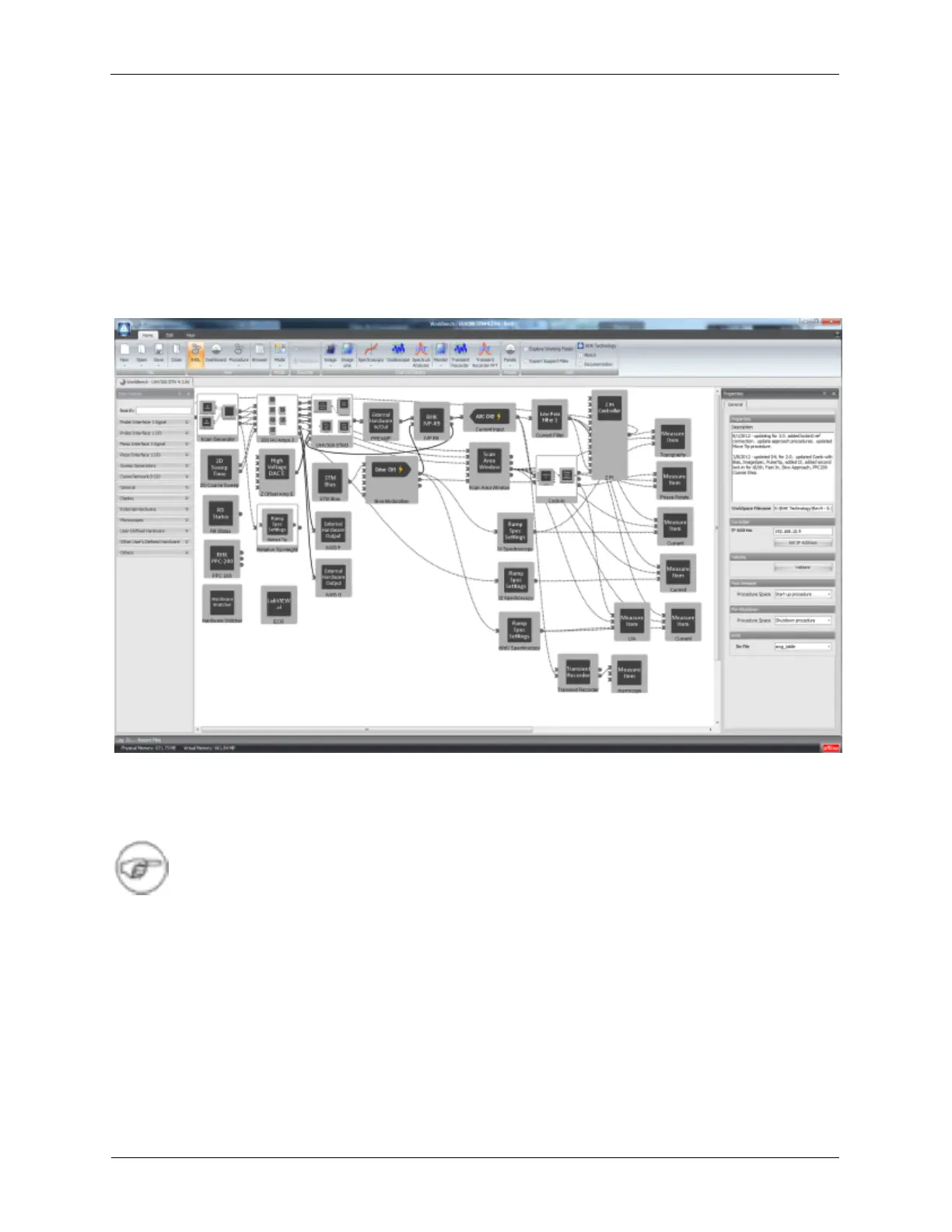
Figure I.1. RHK UHV300 STM IHL
The figure above shows the hardware configuration for the RHK UHV300 STM. Some of the icons in the
diagram may not exactly match those in the R9 version you are using. These differences are cosmetic
and can be ignored.
Note
Solid lines in Hardware Space represent “Real” connections outside of the R9 box. These
are the connections between the R9 and the microscope, preamplifiers, etc. The user is
responsible to make sure these connections are correctly made. Dotted lines in Hardware
Space represent “Virtual” connections inside of the R9 box. These connections are made
when the components in Hardware Spare are connected.
I.1. Scan Processor
The Scan Processor is the firmware component that controls the scanning of the SPM probe. The three
outputs of the Scan Processor, X,Y, and Z are connected to two places:
• Scan Area Window: The SAW icon has inputs for the X, Y, and Z signals from the Scan Processor.
The parameters that are entered into the SAW on the Dashboard are propagated along the virtual