Hardware Space Components
• Logarithmic: The Logarithmic setting subtracts the log of the Input signal from the log of the set point
to generate the error signal. This setting is typically used when the response of the probe to sample
interaction is exponential.
• Divide: The Divide setting subtracts the Input signal from the Set Point and then divides by the Set
Point to generate the error signal. This mode helps to subtracts the effects of increased loop gain due
to increases in Set Point that occurs with the Linear setting.
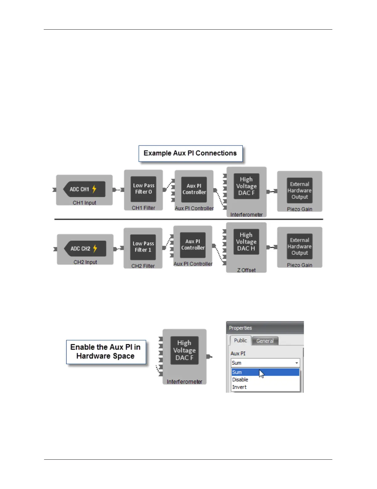
B.7.1. Auxiliary PI Feedback Controller
An Auxiliary PI Feedback Controller can be used for Interferometer Feedback where the interferometer is
mounted on a piezo actuator. Some example connections are shown below.
Figure B.18. Auxiliary PI Feedback Controller
Each High Voltage Amplifier has an Aux PI input. The connected output needs to have the Aux PI
parameter set to Sum or Invert to be enabled.
Figure B.19. Aux PI Input in Hardware Space
The Aux PI has fewer controls than the Z PI feedback controller. There are the Set Point, Proportional
Gain, Integral Gain, and Tip Control.