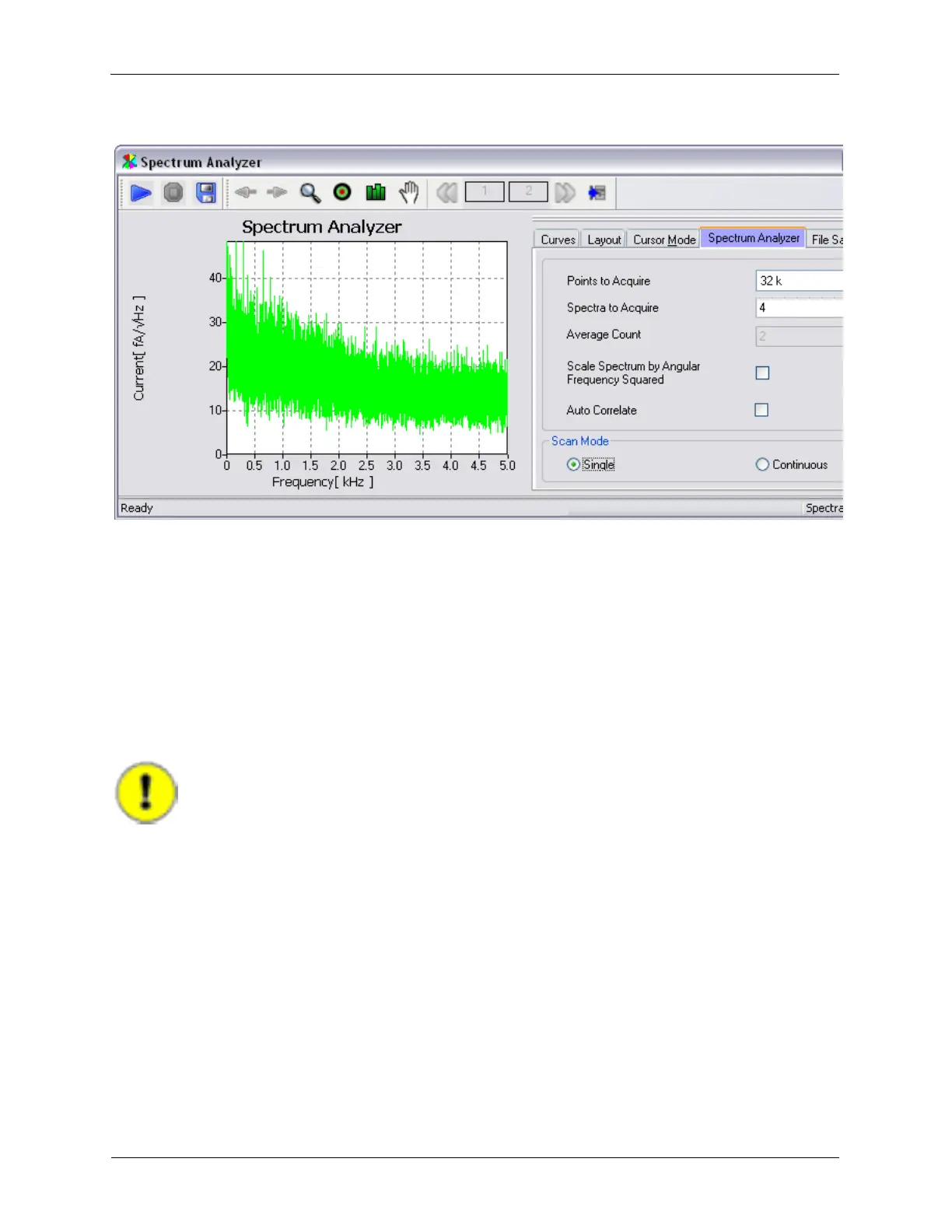
Figure 1.17. Spectrum Analyzer Result with 2 kHz Filter with 48 dB rolloff
1.5.3 Adjusting Bias Voltage Parameters
The Bias Voltage controls in this IHL implementation are part of a larger group of controls based on the
Channel 1 Drive circuitry. In addition to setting the DC value of the bias voltage, controls in the Channel 1
drive circuitry are available to null out DC offsets in the output circuitry, provide an AC modulation of the
Bias Voltage signal for spectroscopic measurements, as well as output scaling circuitry to allow signal
level optimization. As with all R9 controls, only the controls that are required for the desired experiment
need to be visible on the Dashboard.
The first test of the Bias Voltage will require the use of a Digital Volt Meter (DVM). Connect the voltmeter
to the BNC output connector on the IVP-R9 interface module.
Important
Use the highest resolution voltmeter available!
Set the Bias Voltage controls as shown below: