Connecting the Microscope
3. RHK PMC100
4. R9 Computer
5. IVP-R9
6. IVP-300
7. Pan cable set
8. R9 Preamp I/O cable
9. IVP-R9 IVP-300 connecting cable
10. Bias BNC cable
11. R9 PMC100 External Trigger cable
12. Ground cable
13. Ethernet switch
14. Ethernet cables (3)
Connecting the R9 Controller to an RHK UHV900 Pan Microscope:
1. Turn off the R9 Controller.
2. Connect the Ethernet cables: Use the crossover Ethernet cable (typically black) between the
computer and the network switch. Also connect the R9 Controller and PMC100 to the network
switch using the normal Ethernet cables (typically blue).
3. Connect the PMC100 Trigger cable between the R9 Digital I/O #1 and PMC100's External Trigger
BNC.
4. Connect the Pan High Voltage Cable set: this cable set has three 10-pin connectors. Each connector
is keyed differently so there is only one way to connect them. This cable connects to the R9 High
Voltage Output, the PMC100 High Voltage Output, and the 10-pin feedthrough on the Pan
Microscope.
5. Connect the IVP-R9 to the R9 Controller using the Preamp I/O cable.
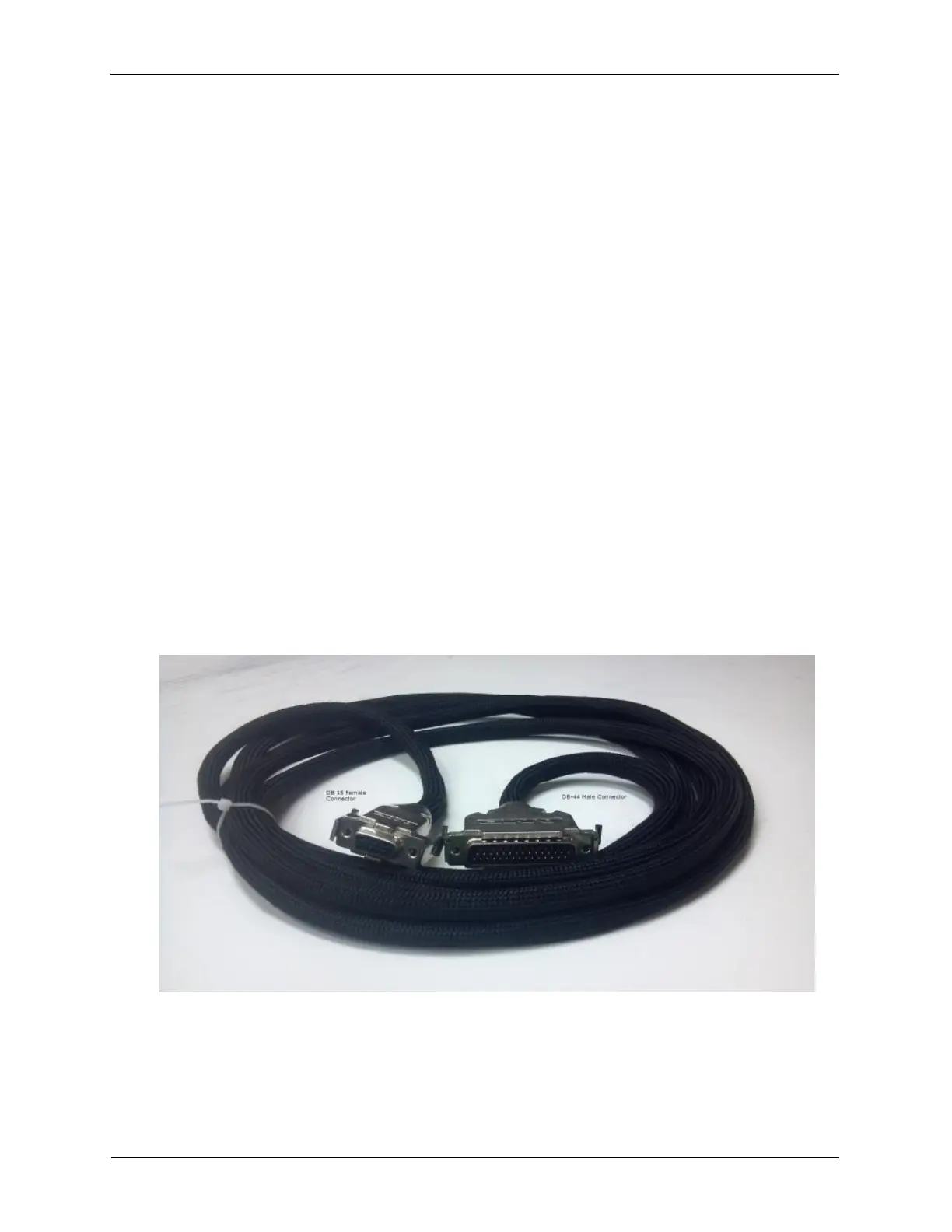
Figure C.6. Combined Bias and Preamp Cable
6. Connect the IVP-R9 to the IVP-300 using the IVP-R9 IVP-300 connecting cable.
7. Connect the IVP-300 to the Pan Microscope. This connection will be either a BNC or SMA connector
that is connected to the STM tip.
8. Connect the IVP-R9 Bias Output to the appropriate BNC connector on the sample stage flange.