Details on an IHL File's Constructions
connection to the Scan Processor. These parameters are used to generate the scanning pattern for
the probe, such as the scan size, speed, position offsets, rotations, etc.
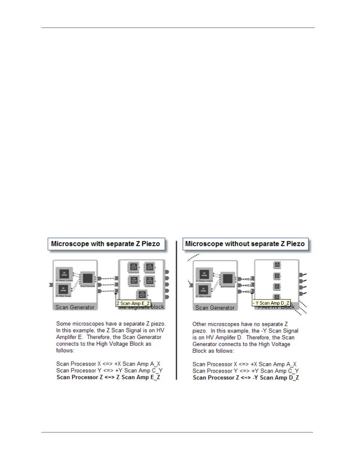
• High Voltage Amplifier block: The HVA block has inputs for the X, Y, and Z signals from the Scan
Processor. The HVA blocks are a composite of individual HVAs configured for specific microscope
designs. Some HVA blocks have four HVAs, some will have five or more. Some HVA blocks have the
Z signal summed into the X and Y scan voltages. Others have a separate HVA for Z scan and/or Z
offset. The X,Y, and Z outputs of the Scan Processor are connected to the X,Y, and Z inputs of the
HVA, respectively.
The virtual connection between the Scan Processor and the HVA is a two way path. The Scan
Processor passes the scanning information to the HVA block to control all aspects of the tip motion. The
HVA block sends the parameters of the microscope that is connected to the HVA outputs (such as piezo
sensitivity in nm/V) to the Scan Processor. These parameters are required for the Scan Processor to
generate the correct size scan. The Parameter for each axis of a piezo scanning element is passed along
the virtual connection for that axis.
• The piezo sensitivity for the X axis is passed from the Microscope icon along the +X virtual connection
to the HVA icon, and then onto the Scan Processor along the X data path.
• The piezo sensitivity for the Y axis is passed from the Microscope icon along the +Y virtual connection
to the HVA icon.
• For Microscopes with a separate Z piezo element, the Z piezo sensitivity is passed from the Microscope
icon along the Z virtual connection to the HVA icon.
• For Microscopes without a separate Z piezo element, the Z sensitivity is passed along the –Y virtual
connection to the Scan Processor.
Figure I.2. Scan Processor Connection to High Voltage Block
The outputs of the HV block that go to the microscope icon represent the connections that go from the
output connections on the rear panel of the R9 Controller to the microscope's piezo scanning elements.
There will be one output for each connection to the microscope. In the above-left example, the HV block
has five outputs: +X Scan, -X Scan, +Y Scan, -Y Scan, Z Scan. In the above-right example, the HV block