Details on Procedure Space Constructions
• Only the first Action icon input pin can be left open. All other Action input pins must be connected to
the output of another Action icon.
• An Action icon output pin can only have one connection. This is required to maintain the deterministic
behavior.
• The final Action icon output pin does not need to be connected. When the procedure reaches the final
Action icon in a State, the State will be exited.
• The output pin of the State must be connected to the input of another State or the Stop icon.
J.2. Connecting Components in Hardware Space and
Procedure Space
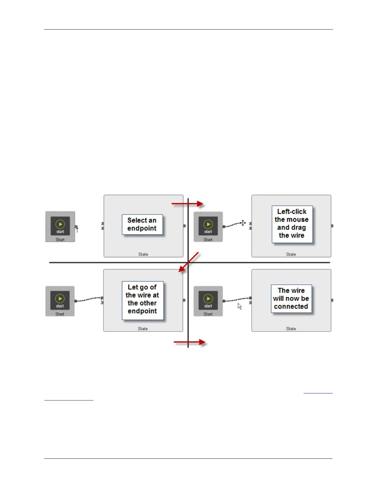
All components in Hardware Space and Procedure Space are connected by virtual wires. To connect
two components together, start by moving the mouse over a component's pin until the cursor symbol
changes from the standard mouse pointer symbol to the arrow as shown in the figure below. Click and
hold the mouse button and drag the “wire” to the desired pin of the next component. While the wire is
being moved, the mouse cursor changes to the cross symbol as shown in the figure below. When the
cursor has been brought on top of the desired connection point, the cursor will again change to the arrow
symbol. Let go of the mouse and the wire will be attached as shown below.
Figure J.3. Connecting Components in Hardware Space and Procedure Space
J.3. Rearranging Connecting Lines
The software routes the wires automatically according to an internal algorithm. It is sometimes necessary
to rearrange the wires to make the signal flow easier to visually follow. To move any wire, first click the
mouse on the wire. It will change from a light dotted line to a heavier dotted line as shown in Figure J.4,
“Selecting a Wire”.