Details on an IHL File's Constructions
another component in Hardware Space, such as the feedback loop or a measure item. Input Channels 3
and 4 utilize different interface logic and are directly connected to measure items.
I.6. Z PI Loop
The Z PI Feedback Loop controls the Z position of the scanning probe. The Signal Output of the Lock-
in Amplifier is connected to the Input pin of the Z PI Loop. The Output pin of the Z PI loop is connected
to the signal pin of a Measure Item, which will send the Topography channel to the PC over the Ethernet
connection. The output pin of the Z PI loop is also connected to the Z input of the Scan Processor.
This final connection closes the feedback control loop. The scan processor propagates the Z signal to the
HVA block. The scan processor can also add a slope correction signal into the Z signal to remove the
effects of a sloped signal from the acquired image.
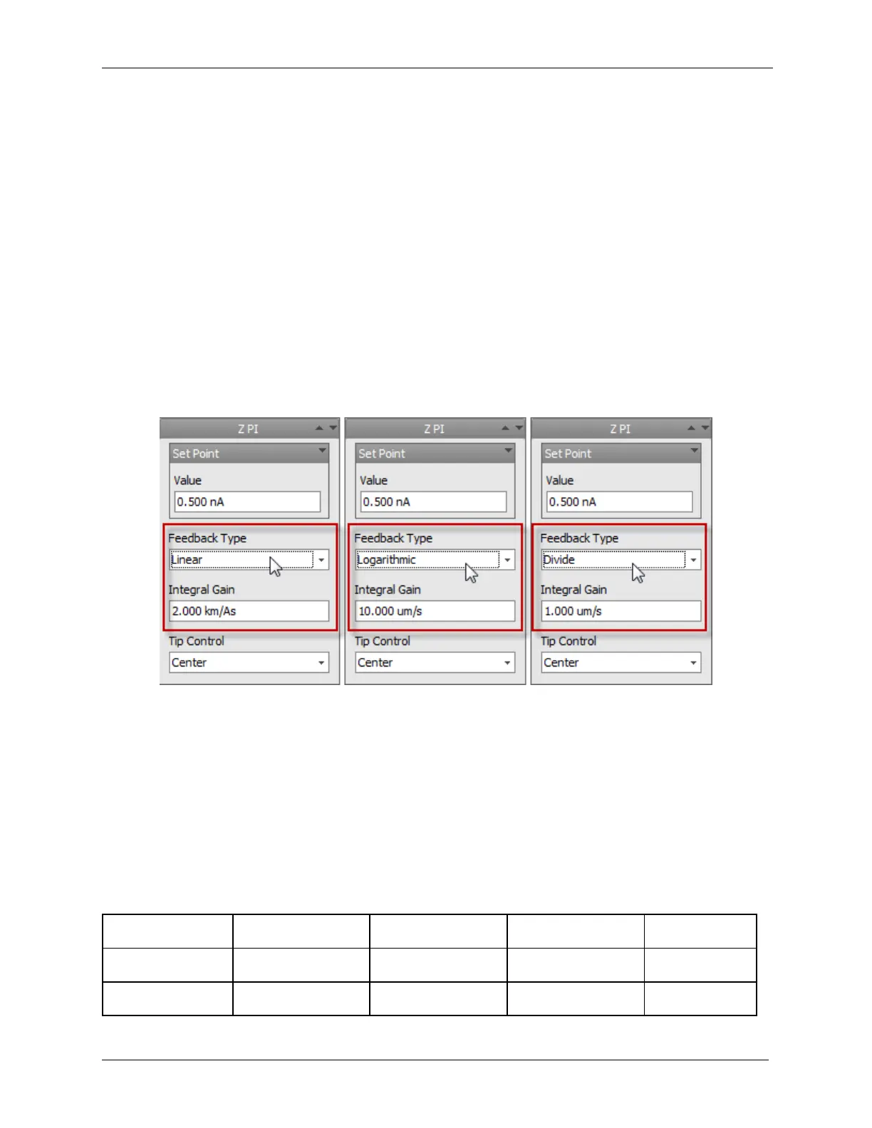
I.6.1. Each Feedback Mode Remembers Gain
Each feedback mode remembers its Integral Gain and Proportional Gain that was last used.
Figure I.3. Setting Gain in Feedback Mode
It is extremely important to take note that the Z PI Feedback Type Logarithmic and Divide modes
have greatly changed in scaling from previous versions by a very large factor. Please check this before
initializing the controller. Initializing with the gains set too high can result in severe feedback
oscillations.
For example, if the Integral Gain was set to 100 m/s with Logarithmic Feedback, it should now be set to
roughly 10 um/s.
The difference in scaling is caused by the necessary changes that were made to the R9 firmware in order
to expand its capability. We apologize for the inconvenience.
Examples