Additional tests can now be performed to demonstrate the modulation capability of the Bias Voltage
circuit.
1. Connect the Bias output of the IVP-R9 Preamp-Bias module to the 100 Megohm Tunnel Gap
Simulator (TGS).
2. Using a BNC cable, connect the other end of the TGS to the input of the IVP-200 preamplifier. If a
preamplifier is used that does not have BNC connectors, follow the procedure shown in the Appendix.
3. Set the Frequency in the Channel 1 Drive to 100 Hz.
4. Set the Oscillation Amplitude to 100 mV.
5. Press the blue start button on the Oscilloscope.
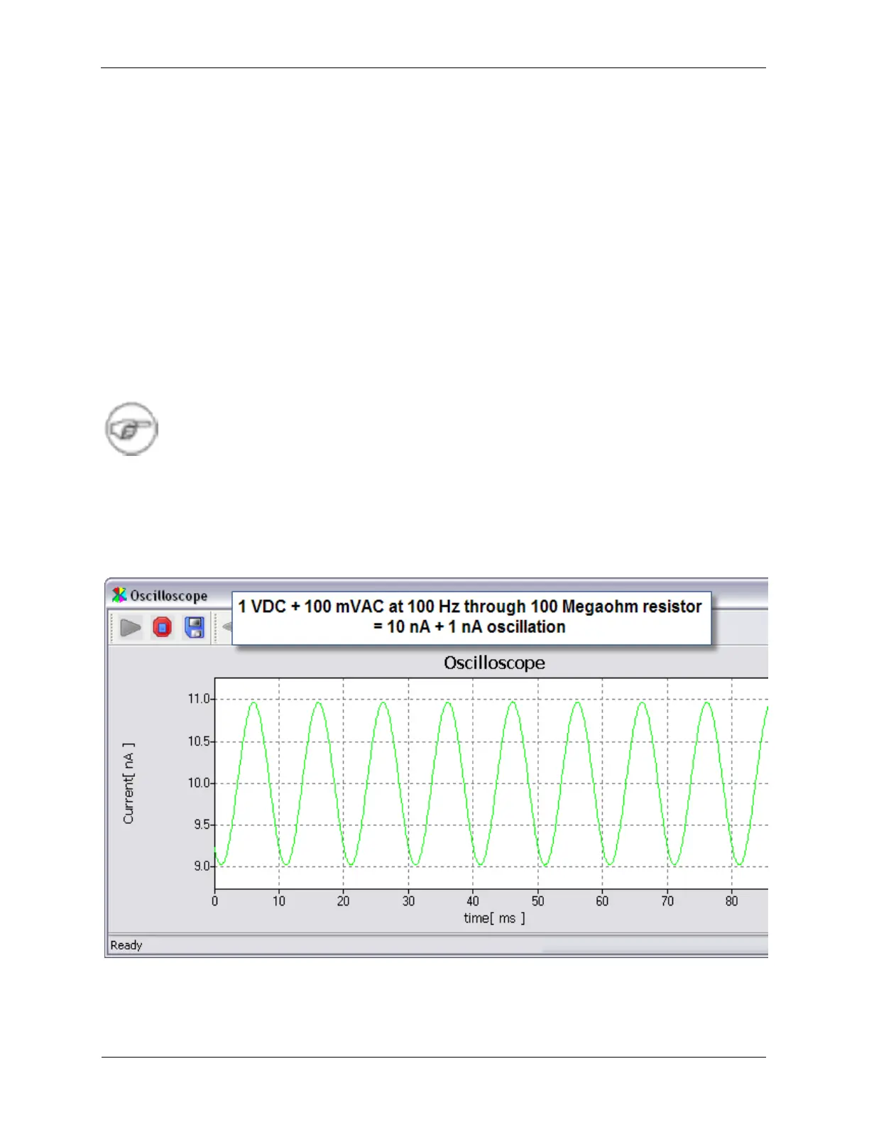
The above settings will add a 100 mV oscillation at 100 Hz to the bias voltage. This voltage will be
converted to a current in the TGS which will then be measured by the IVP-200 preamplifier. The resulting
signal will then be displayed on the oscilloscope.
Note
The amplitude control for the bias modulation is shown as a PEAK value. Peak is the value
of the oscillation from zero to the positive peak of the sine wave. This is one half of the
value that is referred to as Peak to Peak, or P-P.
The Oscilloscope should be displaying a 100 Hz signal with a PEAK value of 1 nA (or 2 nA P-P) that is
centered on the value that is set as the Bias Voltage setting.
Figure 1.19. Bias Modulation through the Tunneling Gap Simulator